• Global CNC market projected to reach $128B by 2028 • New EU trade regulations for precision tooling components • Aerospace deman
NYSE: CNC +1.2%LME: STEEL -0.4%

Why do Shaft Parts fail even when tolerances look right?
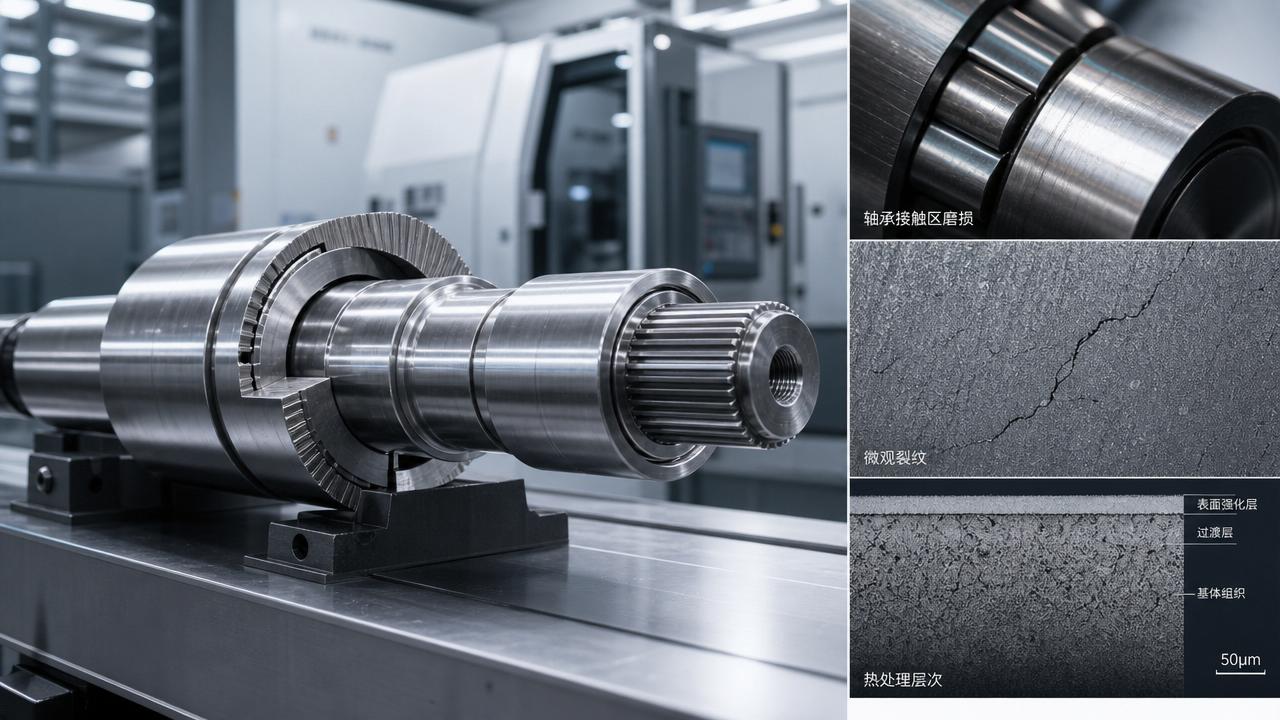
Why do Shaft Parts still fail even when drawing tolerances appear correct? For technical evaluators, the short answer is simple: tolerance compliance confirms only one layer of quality.
A shaft can pass dimensional inspection and still fail in service because performance depends on material stability, surface condition, residual stress, loading mode, assembly fit, and process consistency.
In precision manufacturing, many failures come from factors that are not visible in a basic dimensional report. That is why evaluation must go beyond nominal size and ask whether the part is truly fit for use.
For technical assessment teams, the key task is not just checking whether Shaft Parts match drawings, but whether the entire manufacturing route supports the functional demands of the application.
This article explains the hidden reasons Shaft Parts fail, what technical evaluators should review, and how to identify risk earlier when tolerances look acceptable on paper.
Why “in tolerance” does not always mean “functionally safe”
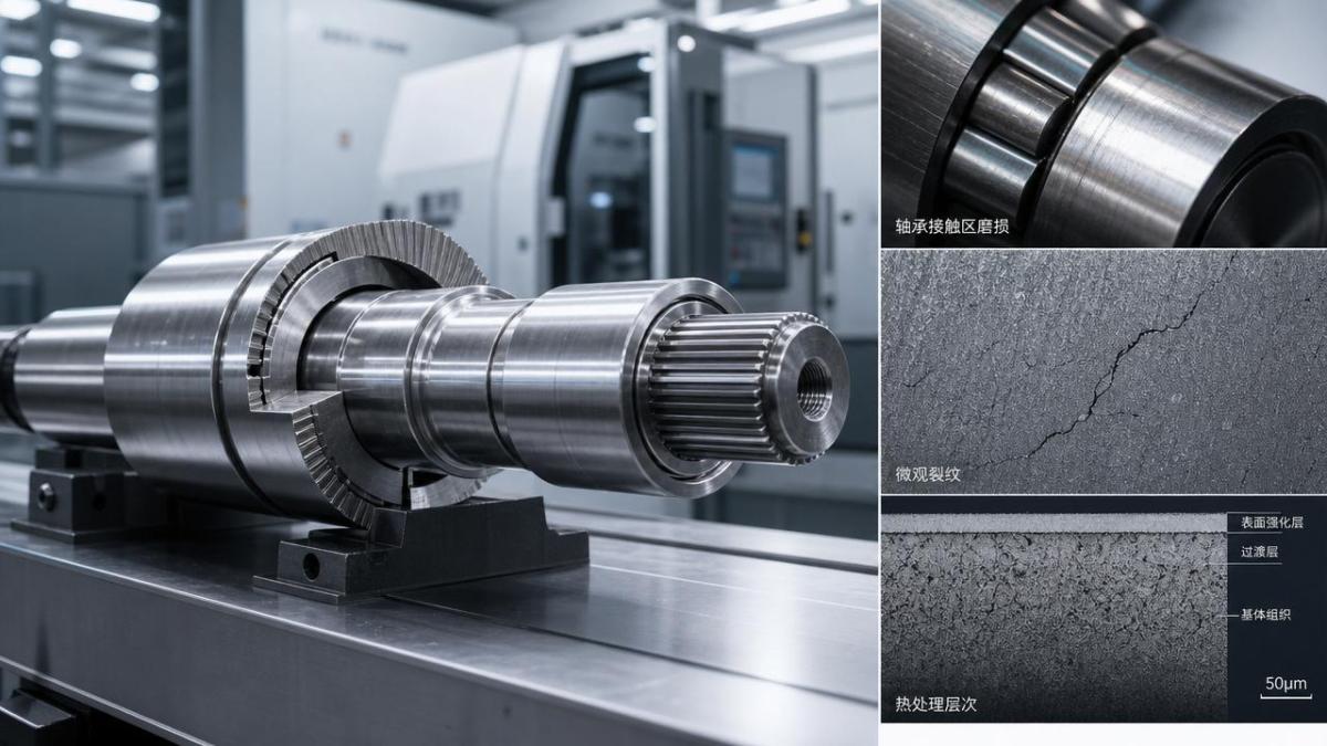
Dimensional tolerance is necessary, but it is not a complete predictor of service life. A shaft works under rotation, bending, torque, contact stress, vibration, and thermal change.
If the drawing controls diameter but not enough related characteristics, the shaft may still suffer fatigue cracking, wear, fretting, seizure, distortion, or premature bearing damage during operation.
Many Shaft Parts are approved because inspection focuses on static dimensions at room temperature. Actual failure, however, happens under dynamic conditions that reveal weaknesses hidden from routine measurement.
For example, a journal diameter may be within size limits, yet poor cylindricity, waviness, or surface pullout can disrupt lubrication film formation and accelerate wear in bearings or seals.
Similarly, a spline shaft may meet dimensional requirements but fail from insufficient core toughness, decarburization, or stress concentration at transition radii that were never adequately evaluated.
The technical lesson is clear: conformance to print does not automatically equal conformance to function. Technical evaluators need to verify whether inspection logic matches the actual failure mode.
Which hidden factors most often cause Shaft Parts to fail?
The most common hidden causes fall into five groups: material issues, surface integrity problems, heat treatment variation, geometric behavior under load, and unstable manufacturing capability.
These factors often interact. A small surface defect may become dangerous only after hardening. A slight runout issue may become critical only when paired with bearing preload or cyclic bending.
Because of that interaction, shaft failure analysis should not isolate one variable too early. A broader systems view usually leads to more accurate technical judgment.
1. Material quality is correct on paper but unstable in practice
A material certificate may meet specification while the actual bar stock still carries segregation, inclusions, inconsistent grain flow, or residual stress from prior processing.
For rotating Shaft Parts, nonmetallic inclusions and internal discontinuities are especially important because they act as fatigue crack initiation sites under cyclic loading.
Technical evaluators should review not only material grade, but also melt route, cleanliness level, ultrasonic inspection requirements, traceability, and consistency between heats or suppliers.
In higher-duty applications, the difference between acceptable and reliable performance may come from steel cleanliness and microstructure control rather than nominal chemistry alone.
2. Surface integrity creates failure even when dimensions pass
Surface integrity includes roughness, waviness, micro-tearing, smearing, burns, residual stress, recast layer, and subsurface deformation created during machining or grinding.
Many Shaft Parts fail because the measured size is correct, but the surface has already been weakened by abusive processing. Grinding burn is a classic example.
A burned surface can introduce tensile residual stress, microstructural transformation, and reduced fatigue resistance. The shaft looks acceptable but becomes vulnerable in real service.
Turning marks, chatter, or incorrect polishing direction can also affect seal life, lubricant retention, and friction behavior. This matters greatly for shaft-seal interfaces and bearing seats.
For evaluators, asking for roughness values alone is not enough. Surface integrity controls, burn detection methods, and process discipline should also be part of supplier review.
3. Heat treatment variation changes performance dramatically
Heat treatment defines hardness, case depth, toughness, dimensional stability, and residual stress state. Minor variation can cause major shifts in shaft durability.
A hardened shaft may satisfy dimensional checks after finish grinding but still fail because the case is too shallow, too brittle, nonuniform, or improperly tempered.
Induction hardening, carburizing, nitriding, and through-hardening each introduce different risks. Distortion, hardness gradients, and transition zones must be assessed in relation to shaft geometry.
Key review points include hardness profile, effective case depth, microstructure, retained austenite limits where relevant, temper response, and control of quench distortion.
When Shaft Parts operate under impact or alternating torque, the balance between surface hardness and core toughness becomes especially important.
4. Concentricity and runout may be acceptable unloaded but unstable in service
A shaft may be measured between centers and appear compliant, yet deflect differently once assembled with gears, pulleys, bearings, thermal growth, and real operating forces.
This is why functional geometry matters more than isolated dimensions. Concentricity, total indicated runout, straightness, coaxiality, and shoulder squareness all influence load distribution.
If bearing seats are nominally correct but misaligned relative to each other, actual contact patterns shift. The result may be vibration, localized heating, noise, or shortened bearing life.
Technical evaluators should ask how geometry is referenced during machining and inspection. Datums that work for measurement may not represent actual assembly conditions.
5. Process capability is insufficient for consistent production
One approved sample does not guarantee stable volume output. Many shaft failures come from variation that appears only across batches, operators, machines, or tool life stages.
If a supplier can hit tolerance only with constant adjustment, the process may be technically capable for prototypes but not robust enough for serial manufacturing.
That means evaluators should look beyond part reports and review Cp, Cpk, gauge reliability, thermal control, tool wear strategy, fixture repeatability, and in-process monitoring.
For critical Shaft Parts, repeatability matters as much as absolute capability. A narrow tolerance is less valuable if the process drifts unpredictably after setup changes or maintenance cycles.
What should technical evaluators review beyond the drawing?
When assessing Shaft Parts, a stronger review framework combines design intent, manufacturing route, inspection method, and service conditions into one evaluation path.
The first question should be functional: what failure mode is most likely in this application? Wear, fatigue, bending, corrosion, fretting, seizure, and vibration require different controls.
Once the main failure risks are defined, evaluators can test whether the drawing and supplier controls actually address those risks. This prevents overreliance on general tolerance compliance.
Review the tolerance stack in relation to assembly function
Not all tolerances carry equal importance. Some dimensions are easy to inspect but have limited impact on performance, while others drive fit, alignment, stress, and fatigue life.
Technical reviewers should identify functional datums, mating interfaces, and tolerance chains affecting bearings, couplings, gears, and seals. That is where hidden failure often begins.
Examine geometry controls, not just size limits
Diameter alone rarely explains shaft behavior. Straightness, roundness, cylindricity, runout, and shoulder relationships often determine whether the shaft will rotate smoothly and carry load correctly.
When geometry controls are weak or inspection methods are inconsistent, a shaft may pass incoming inspection but behave poorly during assembly or endurance testing.
Match material and heat treatment to the real duty cycle
Technical evaluators should compare material and heat treatment not only to specification, but to torque peaks, shock loads, speed, temperature, and required maintenance interval.
A material grade suitable for moderate duty may be inadequate for high-cycle fatigue or marginal lubrication conditions, even if dimensional results remain excellent.
Verify surface-related controls at critical contact areas
Bearing seats, seal tracks, spline flanks, and threaded transitions should receive focused review because those locations are common origins of service failure.
Look for process evidence covering roughness consistency, edge condition, grinding burn prevention, burr control, and surface protection after machining and handling.
Assess supplier process maturity
Reliable Shaft Parts come from controlled systems, not isolated inspection success. A capable supplier can explain process flow, key characteristics, reaction plans, and traceable quality records.
If process knowledge is weak, risk remains high even when initial samples appear good. Technical evaluators should treat poor process transparency as a warning sign.
Why do some Shaft Parts fail only after assembly or field use?
Many failures emerge only after assembly because installation introduces preload, interference, torque transfer, thermal mismatch, and contact patterns that are absent during bench inspection.
For instance, a press-fit section may be dimensionally correct but still generate excessive hoop stress if surface finish, corner radius, or actual material hardness differs from assumptions.
Likewise, a shaft used with bearings may fail due to mounting force damage, poor lubrication alignment, or housing error rather than the shaft dimension itself.
This is why technical evaluation should include interface analysis. A shaft cannot be judged properly as an isolated component when its reliability depends on the surrounding system.
Field failures also expose environmental factors such as corrosion, contamination, shock loading, thermal cycling, and maintenance quality. These can amplify small manufacturing weaknesses into visible breakdowns.
How can evaluators reduce failure risk earlier in sourcing or approval?
The best approach is to shift from print-based acceptance to risk-based evaluation. This means identifying what could fail first, then checking whether manufacturing controls are strong enough to prevent it.
During sourcing, ask suppliers for process flow charts, heat treatment control plans, capability data, inspection strategy, and examples of similar Shaft Parts already produced successfully.
During sample approval, include metallographic checks, hardness profiles, runout verification, surface review, and if needed, fatigue-oriented validation rather than size inspection alone.
During ongoing production, monitor drift indicators such as tool wear patterns, grinding variation, distortion trends, and lot-to-lot material consistency. These signals often appear before failures do.
Where application risk is high, cross-functional review between design, manufacturing, quality, and field service teams is especially valuable. Shaft reliability is rarely controlled by one department alone.
A practical checklist for evaluating Shaft Parts more effectively
For technical evaluators, a useful checklist begins with function. What exact loads, speeds, contact zones, and life expectations does the shaft face in real use?
Then confirm whether the drawing controls those needs through appropriate fits, geometry tolerances, surface specifications, material requirements, and heat treatment definitions.
Next, review whether the supplier process can repeatedly achieve those conditions, not just once but across volume production, shift changes, machine changes, and raw material lots.
Finally, validate whether inspection methods truly detect the likely risks. If the probable failure mode is fatigue, wear, or distortion, dimensional checks alone are not enough.
This approach helps evaluators separate acceptable-looking parts from genuinely reliable Shaft Parts, which is the more meaningful technical decision.
Conclusion: the real reason Shaft Parts fail despite correct tolerances
Shaft Parts often fail even when tolerances look right because dimensional compliance addresses only visible geometry, not the deeper factors that control performance in service.
Material cleanliness, heat treatment quality, surface integrity, functional geometry, assembly interaction, and process capability all influence whether a shaft will survive its intended duty.
For technical evaluators, the right question is not “Did the part meet the drawing?” but “Did the drawing, process, and verification together protect the real failure risks?”
When that broader review is applied, hidden weaknesses become easier to detect, supplier evaluation becomes more accurate, and the chance of premature shaft failure drops significantly.
PREVIOUS ARTICLE
NEXT ARTICLE
Recommended for You
![]() CCMT2026签约汇总:桂林鸿程精机斩获四川振中机电2800万元立车订单
CCMT2026签约汇总:桂林鸿程精机斩获四川振中机电2800万元立车订单![]() 申威数控双主轴对接机床通过德国莱茵TÜV产线集成认证
申威数控双主轴对接机床通过德国莱茵TÜV产线集成认证![]() China's CNC System Export Prices Rise 8.3% in Q1; High-Value Share Hits 42%
China's CNC System Export Prices Rise 8.3% in Q1; High-Value Share Hits 42%![]() First ISO Carbon Footprint Guide for CNC Machine Tools Launched, Accepted Equivalently by China, EU and US
First ISO Carbon Footprint Guide for CNC Machine Tools Launched, Accepted Equivalently by China, EU and US![]() Brazil’s INMETRO IoT Requirement Takes Effect: 37 CNC Lathes Rejected at Santos Port
Brazil’s INMETRO IoT Requirement Takes Effect: 37 CNC Lathes Rejected at Santos Port![]() 红海危机升级致亚欧线舱位冻结:马士基暂停CNC设备订舱,中东买家转向本地化组装
红海危机升级致亚欧线舱位冻结:马士基暂停CNC设备订舱,中东买家转向本地化组装


Aris Katos
Future of Carbide Coatings
15+ years in precision manufacturing systems. Specialized in high-speed milling and aerospace grade alloy processing.
▶
Why do Shaft Parts fail even when tolerances look right?CNC Machining Technology Center▶
Why Shaft Parts fail early and how to prevent itCNC Machining Technology Center▶
How do Shaft Parts defects start during machining?CNC Machining Technology Center▶
What defects in Shaft Parts often trace back to machiningCNC Machining Technology Center▶
What causes hidden defects in Shaft Parts machining?CNC Machining Technology Center
Mastering 5-Axis Workholding Strategies
Join our technical panel on Nov 15th to learn about reducing vibrations in thin-wall components.

Providing you with integrated sanding solutions
Before-sales and after-sales services
Comprehensive technical support