• Global CNC market projected to reach $128B by 2028 • New EU trade regulations for precision tooling components • Aerospace deman
NYSE: CNC +1.2%LME: STEEL -0.4%

Why do Shaft Parts fail quality checks more often than expected?
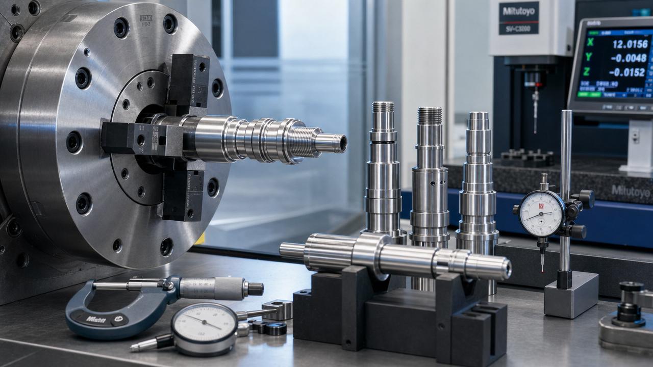
Shaft Parts often fail quality checks more frequently than manufacturers expect, creating risks for product safety, process stability, and delivery performance. For quality control and safety managers, understanding the hidden causes behind dimensional errors, surface defects, material inconsistencies, and machining deviations is essential. This article explores why these failures occur and how better inspection, process control, and CNC manufacturing practices can reduce them.
In CNC machining, shaft components may look simple compared with complex housings or multi-surface structural parts, but they are often among the most demanding items to control. A typical shaft may require diameter tolerance within ±0.01 mm, runout below 0.02 mm, surface roughness between Ra 0.4 and 1.6, and stable hardness across multiple batches. When any of these values drift, the part may still appear acceptable visually while failing functional or safety requirements.
For quality personnel and safety managers, the issue is not only rejection rate. Repeated nonconformity in Shaft Parts can trigger assembly vibration, premature bearing wear, sealing failure, overheating, and even field incidents in automotive, aerospace, energy, or industrial equipment applications. That is why the root causes must be analyzed from drawing interpretation to raw material control, machining setup, inspection method, and supplier capability.
Why Shaft Parts Fail More Often Than Expected in Real Production
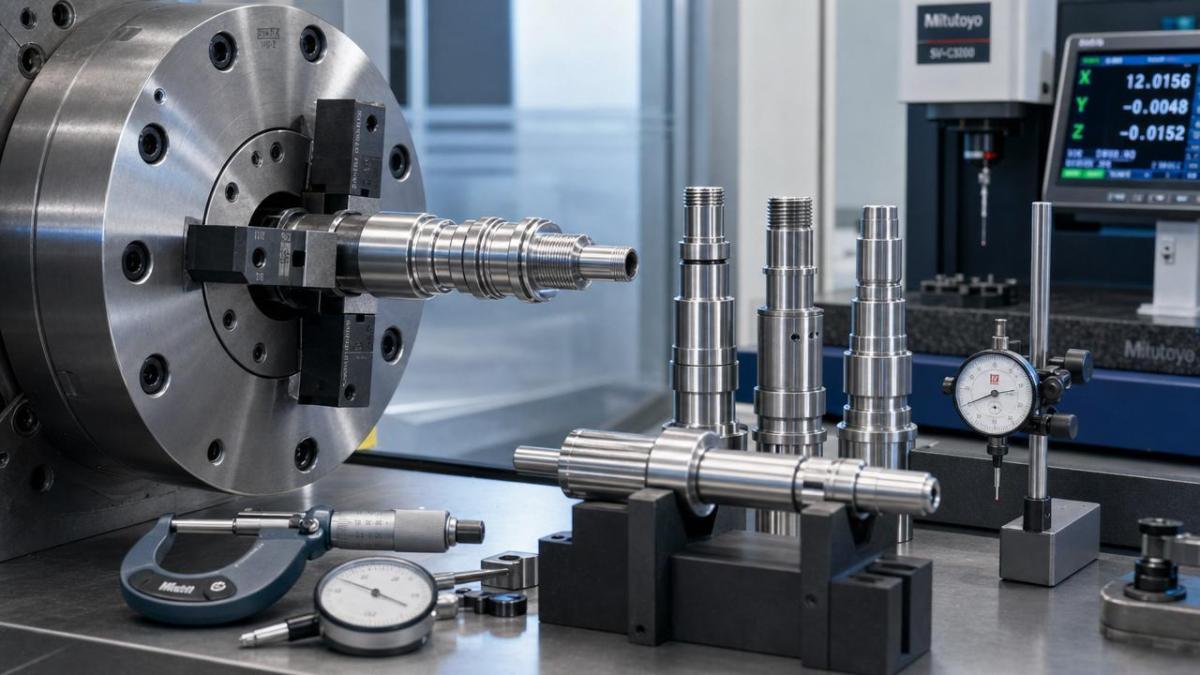
Shaft Parts usually combine several sensitive quality characteristics in one workpiece. A single component may include outer diameters, shoulders, grooves, threads, keyways, concentric surfaces, and heat-treated zones. Even if each individual feature seems manageable, the cumulative tolerance chain often makes the part harder to pass than planners initially estimate.
This challenge becomes sharper in medium- to high-volume CNC production, where 100 to 5,000 pieces may be machined in one batch. Small process shifts that seem harmless during first-piece approval can create a large number of defects after tool wear, thermal growth, fixture fatigue, or material variation accumulate over 4 to 8 machine hours.
Tolerance stacking is often underestimated
Many shaft drawings specify several related dimensions from different datums. If one shoulder position drifts by 0.02 mm and an adjacent diameter drifts by another 0.01 mm, the final assembly fit may already exceed the functional limit. Quality teams often find that the drawing tolerance seems acceptable feature by feature, yet the assembled part fails because cumulative error was not controlled as a system.
Common chain effects in shaft machining
- Diameter error affects bearing fit and vibration level.
- Runout deviation affects rotation stability and seal performance.
- Shoulder location drift changes axial preload or gear alignment.
- Surface roughness variation influences wear, lubrication, and fatigue life.
Long and slender geometry increases process sensitivity
A shaft with a length-to-diameter ratio above 8:1 is much more likely to bend, chatter, or deflect during turning and grinding. Once the ratio reaches 10:1 or 12:1, center support, tailstock pressure, cutting parameters, and tool nose condition become decisive. Without proper support, even a stable CNC lathe can produce taper, chatter marks, or poor concentricity.
This is one reason why Shaft Parts may fail quality checks despite using advanced equipment. Machine capability alone does not guarantee geometric stability if the process design does not match the actual part geometry.
Material behavior is not always consistent batch to batch
Shaft components are commonly produced from carbon steel, alloy steel, stainless steel, and case-hardening grades. Two bars with the same nominal material may still behave differently because of residual stress, grain condition, hardness distribution, or straightness before machining. A bar with higher residual stress may distort after rough turning or heat treatment, causing straightness and runout failure later in the process.
In many factories, incoming inspection checks diameter and material certificate but does not verify bar straightness, hardness range, or internal stress risk. That gap becomes expensive when 20 or 30 finished Shaft Parts must be reworked or scrapped after final inspection.
The table below shows the most common reasons why shaft components fail and how those issues typically appear during inspection.
The key takeaway is that Shaft Parts fail for interconnected reasons, not isolated mistakes. When rejection is treated only as an operator issue, the same defect often returns within 1 to 3 production cycles.
Critical Quality Risks That QC and Safety Teams Should Watch
For quality and safety managers, the most important task is to separate cosmetic nonconformity from function-critical risk. On a rotating shaft, a 0.03 mm runout deviation may be more dangerous than a minor nonfunctional scratch, especially in systems operating at 1,500 to 6,000 rpm. Risk-based inspection helps teams focus on what can lead to field failure, not just what is easiest to measure.
Dimensional errors directly affect assembly and service life
Diameter, length, groove width, and shoulder position must align with mating bearings, couplings, gears, and seals. If a shaft journal is only 0.015 mm oversize, press-fit force may exceed the acceptable range. If it is 0.02 mm undersize, micro-movement may occur during operation, causing fretting, heat, and premature wear.
Geometric errors create hidden safety exposure
Concentricity, coaxiality, roundness, and straightness are often harder to maintain than basic linear dimensions. A shaft may pass diameter inspection with a micrometer and still fail in service because of 0.025 mm runout or 0.03 mm bend over the effective length. In high-speed or high-load applications, this can increase vibration, noise, and fatigue stress significantly.
High-risk inspection points
- Journal diameters used for bearing or seal interfaces
- Datum shoulders controlling axial positioning
- Keyway and spline locations affecting torque transfer
- Thread quality on retention or locking areas
- Runout and straightness over the full effective length
Surface integrity is often judged too narrowly
Many inspections focus only on visible scratches or roughness values. In reality, surface integrity also includes burns from grinding, torn metal from unstable cutting, embedded particles, micro-cracks, and burrs near transitions. A shaft surface with Ra 0.8 may still be unsafe if the process leaves thermal damage or sharp stress risers at a relief groove.
This matters especially in power transmission and hydraulic systems, where one defective edge or damaged seal surface can lead to leakage, abnormal friction, or rotational imbalance.
Heat treatment and hardness inconsistency are major hidden causes
If Shaft Parts require quenching, tempering, induction hardening, or case hardening, quality control must verify more than a single hardness point. Hardness variation of 3 to 5 HRC across different locations may already affect wear performance. Distortion after heat treatment may also push a previously conforming shaft outside straightness or roundness limits.
When production is outsourced across multiple suppliers, this risk becomes higher. One supplier may optimize for hardness while another prioritizes throughput, leading to inconsistent metallurgical results and unstable final inspection data.
Where CNC Manufacturing Processes Commonly Break Down
Most failures in Shaft Parts are not caused by a single dramatic error. They result from routine process weaknesses that remain uncontrolled for days or weeks. The good news is that many of these problems can be reduced through basic manufacturing discipline, especially in CNC turning, grinding, and secondary finishing operations.
Setup repeatability is weaker than many teams assume
Different operators may clamp the same shaft blank with slight variation in jaw pressure, support position, or datum reference. That inconsistency can shift the machining origin enough to affect shoulder location or runout. In high-mix production, where machine changeover may happen 2 to 6 times per shift, repeatability risk increases further.
Tool life control is often based on experience instead of evidence
Some workshops still change inserts only after visual wear becomes obvious. By that stage, dimensional drift may already have affected dozens of Shaft Parts. A better practice is to set a tool life window by material, cutting speed, and finish requirement, such as replacing the finishing insert every 40 to 60 parts or after a defined spindle-time threshold.
Coolant and temperature control influence precision more than expected
Machine thermal growth can change effective cutting conditions during long runs. A shop temperature swing from 20°C to 28°C, combined with unstable coolant concentration, may alter part size, surface finish, and gauge repeatability. For tight-tolerance shafts, thermal stabilization before final measurement is often necessary, especially when tolerance is below ±0.01 mm.
The following table outlines practical process control points for CNC-produced Shaft Parts and their typical monitoring frequency.
The practical lesson is simple: if inspection happens only at the end, CNC shops discover failure too late. When checks are inserted at 3 to 4 control points, scrap and rework on Shaft Parts usually become easier to contain.
How to Reduce Shaft Part Rejections Through Better Inspection and Control
Lower rejection rates start with a control plan built around the real failure modes of Shaft Parts. That means identifying the 5 to 8 characteristics that matter most for function and setting inspection, reaction, and escalation rules before production begins. The most effective quality systems treat shaft machining as a closed loop, not a sequence of disconnected operations.
Build a risk-based inspection plan
Not every dimension needs the same inspection intensity. Critical rotating interfaces, sealing surfaces, and safety-related fit zones may require 100% gauging or automated measurement, while secondary features can follow sampling plans. This prioritization reduces inspection overload and improves defect detection where it matters most.
A practical 4-step control sequence
- Verify incoming bar material, straightness, and certificate consistency.
- Approve first-piece dimensions, runout, and surface condition.
- Monitor in-process drift with fixed intervals and reaction limits.
- Confirm final geometry, hardness, and traceability before release.
Match measuring tools to the feature being checked
A micrometer is useful for diameters, but it cannot reveal full geometric condition. Dial indicators, air gauges, profilometers, roundness testers, height gauges, and CMM verification may all be needed depending on the shaft design. For critical Shaft Parts, measurement system analysis is also valuable because a gauge with poor repeatability can lead to both overreaction and missed defects.
If the gauge variation consumes too much of tolerance, decision quality falls quickly. As a practical rule, many manufacturers aim to keep measurement variation below 10% to 20% of the specified tolerance band for key dimensions.
Strengthen supplier and subcontractor control
When raw material, heat treatment, grinding, or coating is outsourced, quality risk extends beyond the machine shop. QC managers should verify process capability, inspection records, traceability discipline, and response time for nonconformity. A supplier who delivers on time but cannot explain why straightness shifts from 0.01 mm to 0.05 mm is still a serious risk source.
Use production data to prevent recurring defects
Trend charts for diameter, runout, roughness, and hardness can reveal failure before rejection occurs. If the mean dimension moves steadily toward the upper limit over 25 or 50 parts, the process may still be in tolerance but already unstable. Acting at this stage is less expensive than waiting for formal failure.
What Buyers and Decision-Makers Should Ask CNC Suppliers About Shaft Parts
For procurement, quality, and safety teams evaluating CNC suppliers, the right questions can reduce downstream risk significantly. Price and lead time matter, but they should not outweigh process discipline for Shaft Parts that operate under speed, load, or safety-critical conditions. A supplier with low quoted cost but weak inspection capability can create much higher total cost through sorting, delays, and field claims.
Key supplier evaluation questions
- Can the supplier control runout, straightness, and surface finish at the required level?
- What is the in-process inspection frequency during turning, grinding, and heat treatment?
- How are tool life, machine offsets, and batch traceability managed?
- What is the reaction plan if 1 part in 20 fails a critical dimension check?
- Which features are checked 100%, and which follow sampling rules?
Signs of a stronger manufacturing partner
Reliable CNC suppliers usually discuss datums, tolerance stack-up, material condition, and inspection strategy in detail before production starts. They are also able to explain whether a shaft should be turned between centers, supported by steady rest, rough-machined before heat treatment, or finish-ground after hardening. This level of process clarity is often a better indicator than generic quality claims.
In practice, the best results come from suppliers who combine machining capability with disciplined quality feedback. When dimensional trends, process deviations, and corrective actions are shared early, buyers can protect both delivery schedule and operational safety.
Shaft Parts fail quality checks more often than expected because they sit at the intersection of tight tolerances, sensitive geometry, variable materials, and process drift. For QC and safety managers, the most effective response is a structured control system that covers incoming material, CNC setup, in-process verification, post-treatment stability, and final functional inspection. If you are sourcing or improving Shaft Parts for precision manufacturing, now is the time to review your current inspection plan, assess supplier process capability, and close the gaps that lead to hidden rejection risk. Contact us today to discuss your application, request a tailored machining quality plan, or learn more about practical solutions for stable, high-precision shaft production.
PREVIOUS ARTICLE
NEXT ARTICLE
Recommended for You
![]() China's CSF Harmonic Drives Pass ISO 9409-1:2023, Open Import-Substitution Window
China's CSF Harmonic Drives Pass ISO 9409-1:2023, Open Import-Substitution Window![]() Weimait CNC Achieves IATF 16949:2024 Certification
Weimait CNC Achieves IATF 16949:2024 Certification![]() New MIIT Rule: CNC Export Equipment Must Include Multilingual Remote Diagnostics from May 2026
New MIIT Rule: CNC Export Equipment Must Include Multilingual Remote Diagnostics from May 2026![]() CCMT 2026 Concludes in Shanghai: Surge in Five-Axis CNC Export Orders, Lead Times Extend to 14 Weeks
CCMT 2026 Concludes in Shanghai: Surge in Five-Axis CNC Export Orders, Lead Times Extend to 14 Weeks![]() CIMES 2026 Opens in Beijing: Global Buyers Prioritize Smart Production Lines and Export Compliance
CIMES 2026 Opens in Beijing: Global Buyers Prioritize Smart Production Lines and Export Compliance A weak Production Process can raise costs without warningCNC Machining Technology Center



Aris Katos
Future of Carbide Coatings
15+ years in precision manufacturing systems. Specialized in high-speed milling and aerospace grade alloy processing.
▶
Why do Shaft Parts fail quality checks more often than expected?CNC Machining Technology Center▶
Why Shaft Parts fail quality checks more often than expectedCNC Machining Technology Center▶
Why do Shaft Parts fail even when tolerances look right?CNC Machining Technology Center▶
Why Shaft Parts fail early and how to prevent itCNC Machining Technology Center▶
How do Shaft Parts defects start during machining?CNC Machining Technology Center
Mastering 5-Axis Workholding Strategies
Join our technical panel on Nov 15th to learn about reducing vibrations in thin-wall components.

Providing you with integrated sanding solutions
Before-sales and after-sales services
Comprehensive technical support