• Global CNC market projected to reach $128B by 2028 • New EU trade regulations for precision tooling components • Aerospace deman
NYSE: CNC +1.2%LME: STEEL -0.4%

Industrial Robotics for Welding Applications: Which Joint Types Benefit Most?
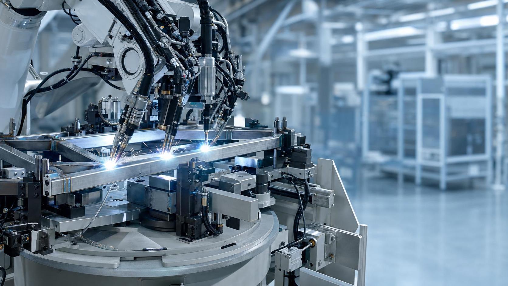
Where Joint Type Changes the Value of Industrial Robotics for Welding Applications
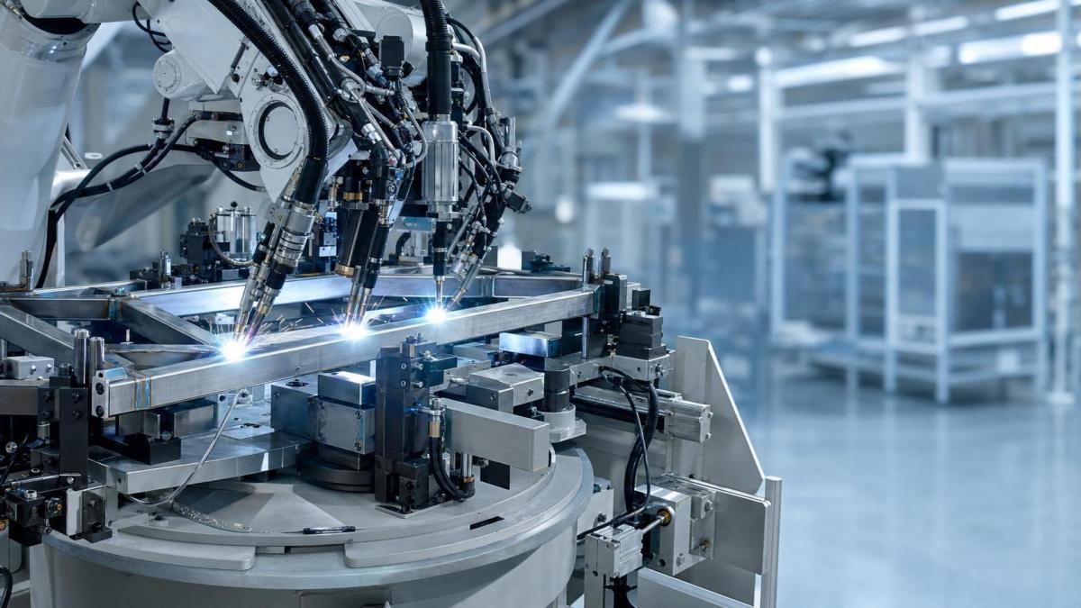
Industrial Robotics for Welding Applications matter most where repeatability, part volume, and geometric consistency directly affect output quality.
That is why joint type cannot be treated as a minor technical detail. It often determines whether automation delivers stable gains or creates new bottlenecks.
In precision manufacturing, welded assemblies increasingly sit beside CNC-machined parts, fixtures, and automated handling systems. Tolerance chains are tighter than before.
A robot can hold torch angle, travel speed, and path position with impressive consistency, but the benefit rises sharply on some joints and only modestly on others.
In practical production, the better question is not whether robotic welding works. It is which joint types justify robotic investment first.
Actual Production Conditions Create Different Priorities
Different sectors ask different things from Industrial Robotics for Welding Applications because part mix, weld access, and quality standards vary widely.
Automotive lines usually favor high-volume, repeatable components. Aerospace often values precision, documentation, and heat control over pure cycle speed.
Heavy equipment and energy assemblies add another layer. Material thickness shifts, fit-up quality may change, and welding positions are rarely identical across every batch.
The broader CNC machine tool ecosystem also matters. When machining centers, fixtures, and robotic cells are coordinated well, robotic welding becomes more predictable.
When upstream cutting or clamping varies too much, even a capable robot cannot compensate for poor joint presentation.
Fillet Joints Usually Deliver the Fastest Robotic Payback
Fillet welds are often the clearest starting point for Industrial Robotics for Welding Applications, especially on frames, brackets, enclosures, and structural subassemblies.
These joints appear frequently in automotive components, machinery bases, agricultural equipment, and fabricated supports used around machine tool systems.
The reason is straightforward. Fillet joints usually offer easier torch access and more forgiving edge preparation than narrow-groove configurations.
Where fixture repeatability is good, the robot can maintain consistent leg size and travel speed, reducing spatter, missed starts, and manual touch-up.
This does not mean every fillet weld is simple. Long joints on large assemblies can distort if heat input is not sequenced carefully.
In actual use, the strongest candidates are repetitive fillet patterns with predictable part loading and limited gap variation.
Where fillet joints fit best
- High-volume fabricated parts with dedicated fixtures
- Assemblies requiring uniform weld appearance across many units
- Cells where CNC-cut blanks already control edge quality well
- Production lines seeking lower rework without complex seam tracking
Butt Joints Benefit Most When Precision Already Exists Upstream
Butt joints can gain a great deal from Industrial Robotics for Welding Applications, but only when preparation and alignment are controlled before welding begins.
This is common in sectors linked to precision machining, including aerospace structures, pressure-related components, and high-spec equipment frames.
A robotic system helps by holding exact path position, weaving pattern, and heat input consistency across long seams.
The challenge is that butt joints are less tolerant of fit-up error. Root gap drift, bevel inconsistency, and plate mismatch quickly undermine automated stability.
In facilities where CNC cutting, edge milling, and fixturing are already mature, robotic butt welding often performs very well.
Where upstream control is weaker, manual intervention or adaptive sensing may still be necessary, which changes the return profile.
Lap Joints Often Make Sense in Thin-Gauge, High-Throughput Work
Lap joints are a strong application area for Industrial Robotics for Welding Applications when thin materials move through repeatable production cycles.
Electronics housings, appliance panels, light vehicle parts, and formed sheet assemblies often fit this pattern.
The main value here is pace plus consistency. Robots maintain stable travel on repetitive weld paths that would otherwise depend heavily on operator rhythm.
Still, overlap geometry needs attention. Excessive coating, oil residue, or inconsistent flange formation can produce porosity or unstable penetration.
More common than expected is a mismatch between welding speed targets and part cleanliness standards. That issue is often mistaken for a robot programming problem.
Corner and Edge Joints Need Better Access Planning Than Many Expect
Corner joints and edge joints can absolutely benefit from Industrial Robotics for Welding Applications, especially in cabinets, tanks, covers, and formed fabrications.
However, these joints are more sensitive to tool access, part deformation, and variable torch orientation around bends or enclosed spaces.
This is where robotic welding decisions become more contextual. A clean digital model does not always reflect real-world access after clamps, stops, and supports are installed.
In shop-floor terms, corner joints work best when fixture designers and robot programmers review the same assembly sequence early.
If they do not, the cell may lose time to awkward reach angles, repositioning, or manual completion of short segments.
Different Joint Types Do Not Ask for the Same Robotic Strategy
The comparison below is useful when evaluating Industrial Robotics for Welding Applications across mixed production lines.
This is why one robotic welding cell may excel on one product family and struggle on another that looks similar on paper.
What Gets Misjudged Before Robotic Welding Goes Live
A frequent mistake is evaluating Industrial Robotics for Welding Applications only by robot payload, reach, or advertised welding speed.
Joint success depends just as much on fixture rigidity, part repeatability, torch access, and upstream dimensional control.
Another common misread is assuming similar joints share the same automation difficulty. A fillet joint on a rigid bracket behaves very differently from one on a heat-sensitive frame.
Cost analysis is also often too narrow. Manual correction, re-clamping, sensor integration, and offline programming time should be counted from the start.
In globally distributed manufacturing, that matters even more because quality standards, operator availability, and part consistency may differ across plants.
A Practical Way to Match Joint Type With Industrial Robotics for Welding Applications
A workable selection method begins with the joint, but it should end with the entire production chain.
- Map weld frequency by joint type across current production families.
- Check whether CNC cutting, machining, and fixturing already hold the needed tolerance level.
- Separate repeatable joints from variable joints before estimating automation benefits.
- Review access conditions with actual clamps and part orientation, not only CAD geometry.
- Test distortion behavior on long seams before locking cycle-time targets.
- Include maintenance, consumables, and programming updates in the economic model.
Where joint families are mixed, many facilities start with repetitive fillet or lap joints, then expand toward more demanding butt or corner applications.
That phased approach usually aligns better with smart factory goals, especially in plants already investing in flexible automation and digital production control.
The Best Results Come From Joint-Level Decisions, Not Broad Automation Claims
Industrial Robotics for Welding Applications deliver the strongest gains where joint geometry, fit-up quality, and production rhythm support repeatable motion.
Fillet joints often lead in early value. Butt joints reward disciplined upstream precision. Lap joints suit thin-gauge throughput. Corner and edge joints demand closer access planning.
For the next step, it makes sense to sort welded parts by joint type, verify actual shop conditions, and compare implementation risk before expanding robotic coverage.
That kind of grounded review is usually more useful than debating automation in general terms, especially in high-precision manufacturing environments.
Recommended for You
 How to Select an Industrial Lathe for High-Volume Shaft ProductionMachine Tool Industry Editorial Team
 Selecting Machine Tools for Automotive Parts: Accuracy, Throughput, and AutomationMachine Tool Industry Editorial Team
 Industrial Machining: Selecting Processes for Tight-Tolerance Metal PartsCNC Machining Technology Center
 Manufacturing Technology Trends That Improve Throughput and Quality ControlManufacturing Market Research Center
 How to Design Cost-Effective Fixtures That Maintain Cycle Time in Mass ProductionCNC Machining Technology Center
 Is Learning CNC Programming Worth It for Shop Owners Seeking Higher Margins?CNC Machining Technology Center

Aris Katos
Future of Carbide Coatings
15+ years in precision manufacturing systems. Specialized in high-speed milling and aerospace grade alloy processing.
▶
Selecting Machine Tools for Automotive Parts: Accuracy, Throughput, and AutomationMachine Tool Industry Editorial Team▶
Smart Manufacturing for Small Businesses: Where Automation Delivers the Fastest ROIMachine Tool Industry Editorial Team▶
How Smart Manufacturing Technology Improves OEE Across Industry 4.0 Production LinesMachine Tool Industry Editorial Team▶
How to Evaluate an Automation Line for Electronics Production Before InvestmentMachine Tool Industry Editorial Team▶
How to Evaluate an Automated Production Line for Output, Flexibility, and ROIMachine Tool Industry Editorial Team
Mastering 5-Axis Workholding Strategies
Join our technical panel on Nov 15th to learn about reducing vibrations in thin-wall components.

Providing you with integrated sanding solutions
Before-sales and after-sales services
Comprehensive technical support