• Global CNC market projected to reach $128B by 2028 • New EU trade regulations for precision tooling components • Aerospace deman
NYSE: CNC +1.2%LME: STEEL -0.4%

Choosing CNC Production Equipment for High-Volume Parts Manufacturing
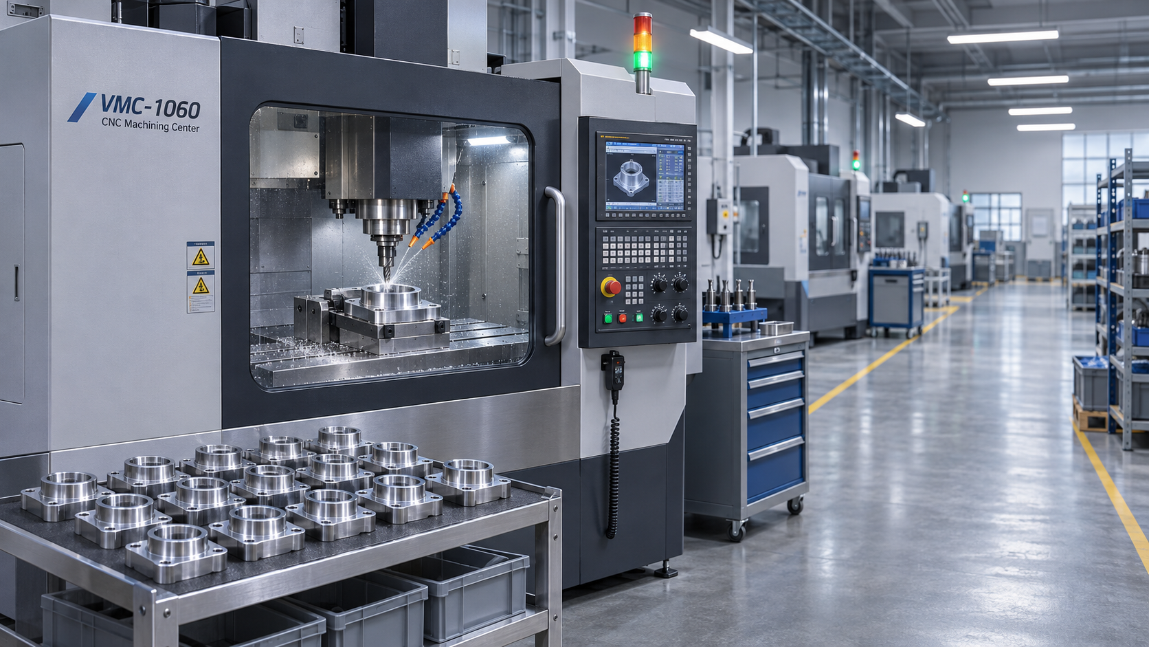
Choosing CNC production equipment for high-volume parts manufacturing requires more than comparing spindle speeds or quoted cycle times. The decisive question is whether the complete production system can deliver conforming parts at the required rate, over the intended production period, with acceptable downtime and cost.
A machine that produces the fastest individual cut is not necessarily the best production choice. Loading time, tool changes, thermal drift, chip evacuation, inspection and recovery from interruptions can determine whether its theoretical advantage survives a full shift. Equipment selection should therefore begin with the part, the required output and the process conditions—not a preferred machine configuration.
Translate production demand into a usable cycle-time target
Annual part volume alone is not enough to size a CNC cell. Convert demand into a required production rate using scheduled operating time, then account explicitly for planned losses and expected interruptions. Changeovers, preventive maintenance, tool replacement, inspection and breaks may reduce the time available for cutting or part handling.
For example, an illustrative requirement of 120,000 acceptable parts per year over 4,000 scheduled hours represents 30 good parts per scheduled hour, or one every 120 seconds. If only 80% of scheduled time is available for production, the rate during available time must rise to 37.5 good parts per hour, equivalent to 96 seconds per good part. If the process yield is below 100%, the machine must produce additional pieces to compensate. The availability and yield assumptions should be validated against the intended process rather than treated as machine guarantees.
Distinguish between cutting time, machine cycle time and cell output interval. A quoted machining cycle may exclude robot transfer, part clamping, probing, tool-life checks or operator intervention. In a multi-operation line, output is constrained by the bottleneck operation and its interruptions, not by the average cycle time across all machines.
The part mix matters as much as the volume. A dedicated process can justify specialized fixtures and carefully balanced operations when demand is stable. If the equipment must accommodate several variants, setup time, fixture exchange, program management and the capacity lost during changeovers belong in the rate calculation.
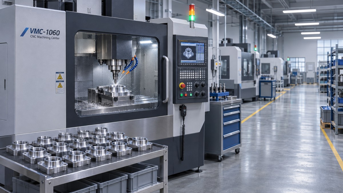
Match the machine architecture to the part and process
Start with the part’s datum structure, material, stock form and features. The best configuration minimizes costly handling and quality risk without adding capabilities that the process cannot use.
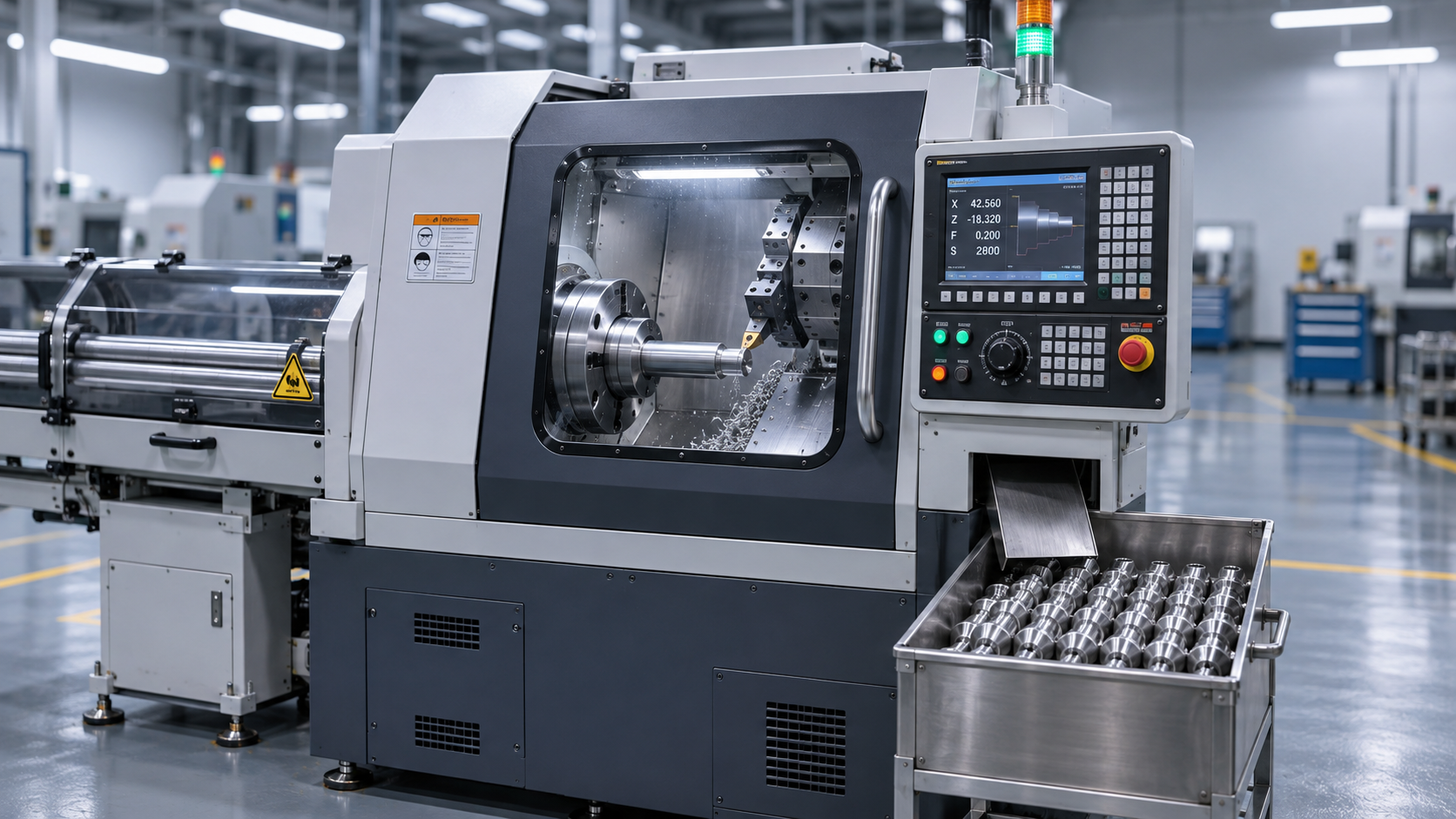
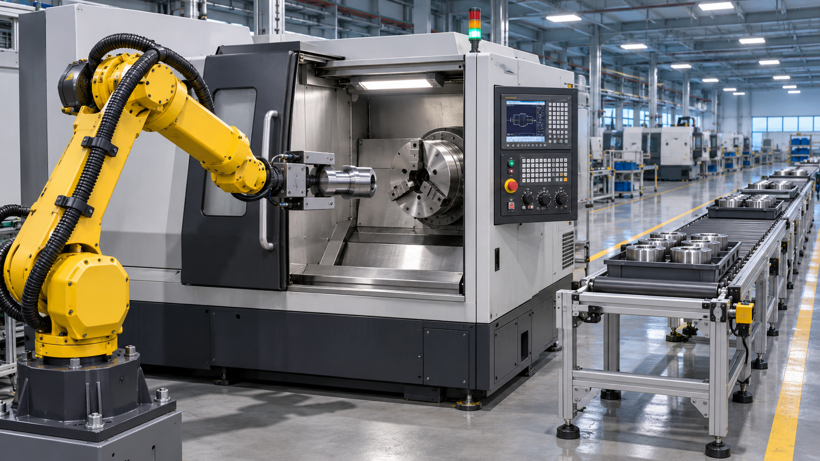
For rotational parts such as shafts or discs, a turning center is a logical starting point. Live tooling and a Y-axis can machine off-center holes, flats or slots without a separate milling operation. A sub-spindle can transfer the part for reverse-side work, reducing manual handling. These features add value when they remove a genuine bottleneck or improve control of features across setups; they also increase programming, tooling and recovery complexity.
For prismatic or structural parts, a vertical machining center offers access for many top-facing operations, while a horizontal machining center can support multi-face work on tombstone fixtures and assist chip evacuation. The choice depends on feature access, part size, workholding, tool reach and the number of parts processed per loading cycle. A five-axis machine can reduce re-clamping for features on multiple faces, but it is not automatically faster or more accurate than a simpler machine dedicated to a stable operation.
High-volume work can also favor multiple simpler machines over one highly integrated machine. Splitting operations may allow parallel production and isolate failures, although it increases transfers, floor-space demand and the number of interfaces that must be controlled. Conversely, combining operations can reduce work-in-process and datum transfers, but a failure on the combined machine can stop more of the process. Compare both arrangements using line output and recovery behavior, not machine count alone.
Evaluate cutting capability under the intended load
Spindle speed is useful only in relation to cutter diameter, material and the required cutting speed. Power and torque curves matter across the operating range: a machine may advertise high peak power but have a different continuous rating, or deliver its maximum torque outside the speed range used by the process. Heavy roughing, small-diameter finishing and interrupted turning impose different demands.
Assess the entire cutting system, including spindle bearings, toolholder interface, turret or spindle nose, axis drives, workholding and tool projection. A long boring bar or a thin-walled component can limit material removal well before the machine reaches its rated power. In such cases, a larger machine does not necessarily solve the problem; tool geometry, support, cutting strategy or operation sequence may matter more.
Axis acceleration, rapid traverse and tool-change time can materially affect short cycles with many non-cutting movements. Compare these values with the actual program’s travel distances and tool sequence. A high rapid-traverse rating gives little benefit if axes travel only short distances and spend much of that movement accelerating and decelerating.
Check practical capacity rather than nominal travel alone. The usable envelope must accommodate the part, fixture, clamps, tooling and safe approach paths. On a lathe, include chuck and jaw dimensions, bar or billet length, tailstock or sub-spindle travel, and clearance for chip flow and part removal.
Specify accuracy as a production requirement
A positioning specification does not establish that a machine will hold a finished-part tolerance throughout a shift. Part accuracy depends on thermal behavior, cutting forces, fixture repeatability, tool wear, measurement methods and the sequence in which features are machined.
Identify the dimensions and geometric relationships that control function, then determine which require the same setup or datum transfer. A concentricity requirement between features machined at opposite ends of a part, for example, depends not only on machine geometry but also on how the part is gripped and transferred. For thin-wall work, clamp distortion and the order of material removal can dominate the final result.
Request evidence that reflects the intended operating conditions. A useful production trial defines the material, stock condition, tooling, fixture, program, coolant, warm-up procedure and measurement method. It should include consecutive parts over a representative operating period, rather than only a single carefully adjusted sample. Review startup behavior, offsets, tool changes and the effect of normal interruptions as well as the final measurements.
Capability measures such as Cp and Cpk can support acceptance when the characteristic, sampling plan, measurement system and calculation method are agreed in advance. Their interpretation depends on a stable process and representative data; a short trial cannot by itself establish long-term capability across tool wear, ambient changes and maintenance cycles. Where tolerances are tight, evaluate measurement uncertainty and the resolution and repeatability of gauges before attributing variation to the machine.
Design automation around the complete part flow
Automation should be selected after the loading sequence and failure conditions are understood. Bar feeders suit eligible turned parts made from bar stock, while gantries, robots, pallet systems and dedicated loaders address different combinations of part geometry, access and production mix. Their value depends on whether they reduce the constraint in the process.
Confirm that the proposed loading time can be overlapped with machining where the architecture permits it. A robot serving several machines must complete travel, gripping, loading, unloading and any intermediate checks within the required schedule. One slow operation or a blocked discharge can cause the robot to wait or prevent another machine from being serviced.
Gripper design must accommodate stock variation, part orientation, surface protection and the presence of coolant or chips. Fixtures need reliable confirmation of clamp state and, where necessary, part seating. Consider how rejected parts are identified and segregated, how tool-life limits trigger a controlled stop, and what happens after a power interruption or a failed pick. Manual access for setup and maintenance must remain practical once guarding and conveyors are installed.
Chip management deserves the same attention as loading. Material, chip shape, coolant delivery and conveyor layout affect whether swarf clears the cutting zone and the machine enclosure. A process that achieves its target cycle but requires frequent manual chip removal has not demonstrated its intended unattended capacity.
Control integration should be defined at the interface level: machine-ready signals, door and chuck states, alarm handling, cycle initiation, part counts and recovery sequences. Data connectivity is useful only when the required signals and their meanings are agreed, accessible and tested across the equipment involved.
Compare tooling and workholding as part of the machine investment
High-volume production magnifies small differences in consumable life and intervention time. A tool that saves a few seconds per part may be less economical if it requires frequent changes, creates unpredictable wear or increases scrap near the end of its life. Evaluate cost per accepted part using tool life under the proposed cutting conditions, including insert changes, presetting and lost production during replacement.
Workholding should be assessed for repeatable location, clamping force, access and chip clearance. Hydraulic or pneumatic fixtures can reduce handling time, but they require reliable pressure control, sensing and maintenance. Multi-part fixtures increase output per load only if the machine has sufficient tool capacity, travel and process stability to complete the longer unattended cycle.
Tool-magazine capacity is another practical constraint. Count sister tools, probes, special tools and the tools needed for all part variants—not just those used in the nominal program. If the required set exceeds capacity, tool exchange or duplicate machines may change the economics of the proposed configuration.
Build the cost comparison around conforming output
Purchase price is only one part of the decision. Compare alternatives over the same production horizon and demand assumptions, using expected cost per accepted part. Include machine and automation investment, installation, fixtures, tooling, programming, labor, energy, maintenance, consumables, inspection, scrap and the capacity consumed by downtime and changeovers. Financing and residual value can be included where relevant to the investment method.
A higher-priced machine may be justified by fewer operations or lower labor requirements, but only if those savings are achievable at the required volume. Conversely, the lower-priced option may require an additional setup, more floor space or a separate handling system. Avoid counting the same saving twice—for example, claiming both a lower cycle time and a labor reduction when the operator remains occupied elsewhere in the cell.
Test the comparison against changes in demand, tool life, availability and yield. If one option is attractive only at maximum utilization with no allowance for recovery, its apparent advantage is fragile. Include the effect of spare capacity: it may raise initial investment but can protect delivery when maintenance, scrap or a demand increase consumes the planned margin.
Define acceptance before ordering
A useful equipment specification connects each major claim to a measurable acceptance condition. Define the representative part and material, required output, allowable interventions, critical characteristics, sampling method and measurement equipment. State which elements are included in the demonstrated cycle, from loading through unloading, and distinguish a short machine trial from a longer production-rate demonstration.
Agree on responsibilities for tooling, fixtures, programs, automation interfaces and utilities. If the supplier demonstrates a cycle with a fixture or cutting tool that will not be used in production, the result may not transfer to the installed process. Site conditions—including power, air, coolant, extraction, foundation and available floor space—also need to match the agreed configuration.
The strongest selection is the one whose assumptions can be checked: a feasible part process, a rate calculation that includes losses, evidence for critical quality characteristics, and an automation concept with defined recovery behavior. Those conditions make it possible to compare machines on the output they can sustain, rather than on specifications viewed in isolation.
Recommended for You
![]() Perpetua Resources Signs MOU to Evaluate US Tungsten Supply ChainManufacturing Market Research Center
 Choosing an Automated Lathe: Bar Capacity, Accuracy and Production VolumeCNC Machining Technology Center
![]() US Cutting Tool Shipments Reach $287.6 Million in September 2026Machine Tool Industry Editorial Team
 Choosing a Machine Tool Supplier: Service, Lead Times and Total CostManufacturing Market Research Center
![]() India Announces Domestic Five-Axis CNC Machine With 2-Micron AccuracyMachine Tool Industry Editorial Team
 Integrating Industrial Automation into Existing Production Lines: Key StepsMachine Tool Industry Editorial Team


Aris Katos
Future of Carbide Coatings
15+ years in precision manufacturing systems. Specialized in high-speed milling and aerospace grade alloy processing.
▶
India Announces Domestic Five-Axis CNC Machine With 2-Micron AccuracyMachine Tool Industry Editorial Team▶
Choosing CNC Production Equipment for High-Volume Parts ManufacturingMachine Tool Industry Editorial Team▶
Zhongshan Xiaolan Machinery Exhibition Opens With Global Product DebutsMachine Tool Industry Editorial Team▶
Mitsubishi Electric Announces Physical AI System Linking Humanoid Robots and CNC MachinesMachine Tool Industry Editorial Team▶
Japan Adds 5-Axis CNC Gear Grinders to Export ControlsMachine Tool Industry Editorial Team
▶
Mastering 5-Axis Workholding Strategies
Join our technical panel on Nov 15th to learn about reducing vibrations in thin-wall components.

Providing you with integrated sanding solutions
Before-sales and after-sales services
Comprehensive technical support