• Global CNC market projected to reach $128B by 2028 • New EU trade regulations for precision tooling components • Aerospace deman
NYSE: CNC +1.2%LME: STEEL -0.4%

Integrating Industrial Automation into Existing Production Lines: Key Steps
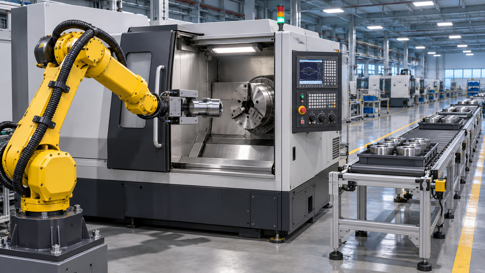
Successful automation integration starts with a defined production constraint and a realistic plan for connecting new equipment to the existing line. Establish where parts wait, how machines exchange signals, and which interruptions limit output before selecting robots, conveyors, or control software. Then design the installation around actual machine cycles, available downtime, safety functions, and a recovery path for when equipment stops.
For a CNC production line, the most difficult work often occurs at the interfaces: presenting a part in the right orientation, confirming that a chuck has gripped it, coordinating a machine door with a robot, and keeping part identity intact after a fault. Resolving those details early makes the difference between an automated demonstration and a line that can run reliably across shifts.
Establish the production baseline
Map the current flow from raw material entry to the next downstream operation. Record the sequence of machining, inspection, loading, unloading, washing, and buffering, including movements performed manually. Identify where parts accumulate and where machines wait for material. A station with a long cycle time deserves attention, but it is not automatically the constraint: frequent stops, tool changes, or an unreliable upstream process can have a greater effect on completed output.
Measure performance over representative production periods rather than relying only on nameplate capacity or an isolated cycle-time trial. Capture cycle time, changeover duration, availability, scrap and rework, and the causes of interruptions. Separate planned downtime from unplanned stops and distinguish machine cutting time from the time spent opening doors, exchanging parts, and confirming inspection results.
Product mix matters. A robot designed around one stable component may struggle when future parts require different gripping surfaces or when a fixture change alters the loading position. Record the range of part dimensions, weights, surfaces, tolerances, and orientations, along with the frequency of changeovers. Include unstable conditions such as mixed batches, worn fixtures, and parts arriving with chips or coolant on locating surfaces.
Use the baseline to set an acceptance target for the entire flow. For example, define output as conforming parts delivered to a specified downstream point during an agreed operating period. State the product mix, staffing assumptions, planned stoppages, and measurement method. A faster machine cycle alone does not demonstrate an improvement if inspection, material supply, or recurring faults keep total output unchanged.
Define the scope around the constraint
Choose the first automation boundary where the expected change can be measured and where upstream and downstream conditions can support it. Automating CNC loading is a logical candidate when a machine waits consistently for part exchange and the part can be gripped and located repeatably. If the machine already cuts continuously while finished parts queue for inspection, automating loading will have limited effect until inspection capacity is addressed.
Document what the new cell must handle: part variants, incoming presentation, outgoing orientation, required traceability, available floor space, utilities, and the maximum acceptable interruption during installation. Define which operations remain manual and where responsibility passes between existing controls and new equipment. Include ordinary production as well as startup, changeover, tool replacement, part rejection, and recovery after a stop.
Consider buffers as part of the process design. A buffer can absorb short disturbances between stations, but it also occupies space and can hide a recurring fault. Its useful capacity depends on the duration of interruptions it is intended to absorb, the rate at which parts enter and leave, and whether parts can wait without damage or loss of identification. A buffer cannot compensate indefinitely for a downstream station whose sustained capacity is lower than upstream output.
Resolve machine and control interfaces before design freeze
Create an interface map for each CNC machine and connected device. Identify the control system, available communication methods, electrical interfaces, door and chuck functions, existing interlocks, and the signals needed for automatic operation. Review machine documentation and confirm actual behavior on the installed equipment; options shown in a generic manual may not be enabled or fitted on a particular machine.
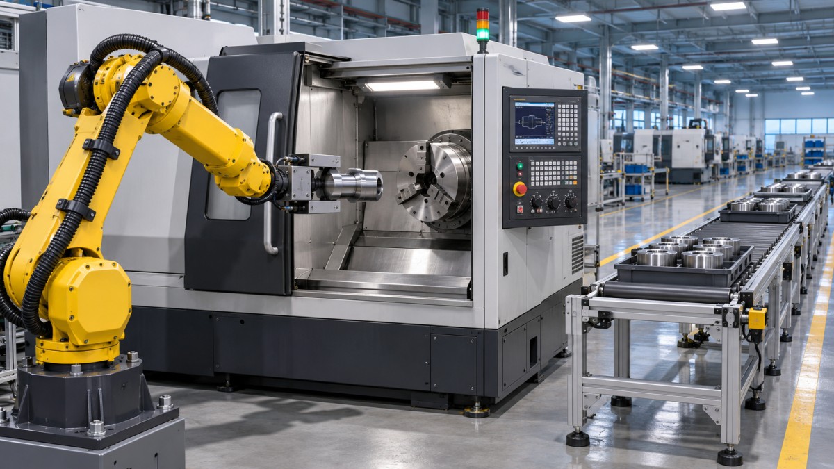
For a robot tending a lathe, a basic sequence might require the CNC to confirm that the spindle is stopped, the door is open, and the chuck is in the expected state before the robot enters. After loading, the system must confirm that the robot has cleared the work envelope, the door has closed, and the part is clamped before a cycle can start. Each confirmation needs a defined source, destination, and response if it fails to arrive.
A signal described as “ready” is rarely sufficient by itself. Specify whether it means the machine is powered, free of alarms, in automatic mode, or physically ready to receive a part. Define timeouts, fault messages, reset conditions, and ownership of each command. Also document what happens if power or communications are lost while a part is held by the robot or clamped in the machine.
Legacy machines may offer limited digital inputs and outputs rather than detailed production data. That can be adequate for a narrowly defined loading sequence if the required states are available and reliable. Where additional sensing or machine modification is needed, verify the effect on existing control functions and safety arrangements before work begins. Extracting data for a dashboard should not interfere with the control path that keeps the process operating.
Design the physical exchange around real parts
Part handling must accommodate the surfaces and process conditions found at the machine, not just the nominal drawing. A gripper that locates accurately on a clean blank may slip on a coolant-coated surface. Thin-walled components can distort under excessive grip force, while rough castings may present inconsistent contact points. Test representative parts, including expected variation, and define how an unsuitable part is detected and removed from the flow.
Review access with the door open, the chuck or fixture installed, and the tool turret or spindle in its actual loading position. Include gripper fingers, hoses, cables, and the part itself in the clearance study. A path that works in a simplified model can fail because of a protruding jaw, a coolant nozzle, or the space required to rotate a component inside the enclosure.
Decide where chips and coolant are controlled. Chips on a fixture face can prevent a part from seating; an automated cycle may then repeat the error until the condition is detected. Air blow-off, cleaning, seating confirmation, and inspection can reduce exposure, but their effectiveness needs to be demonstrated with the material and chip form produced by the process. Plan for coolant drainage and collection so that transferred fluid does not create slip hazards or contaminate downstream equipment.
Changeovers deserve the same attention as normal cycles. Record how grippers, jaws, nests, programs, and offsets are selected and verified for each part family. A quick physical change is of little value if the wrong recipe can be started afterward. Part identification and a clear confirmation of the active program reduce the chance of a mismatch between tooling and CNC settings.
Integrate safety into the operating sequence
Assess hazards across the complete cell, including robot motion, machine axes, automatic doors, conveyors, stored energy, and access for clearing jams. The assessment should cover routine production and foreseeable interventions such as removing a misloaded part, changing a gripper, or cleaning chips from a fixture. Existing safeguards need to be considered together with the new equipment because their interaction can create access paths or unexpected restart conditions.
Define the protective functions and the conditions under which motion is permitted. Guarding, interlocked access, emergency stops, and other protective measures must be selected and validated for the actual hazards and applicable local requirements. An emergency stop is not a substitute for a controlled energy isolation procedure during maintenance.
Recovery procedures should identify the safe state of every device, the location and ownership of the part, and the sequence for returning to automatic operation. For example, after an interrupted unload, the control system needs a way to distinguish a part still in the chuck from one held by the gripper. If that state cannot be established reliably, recovery must require a deliberate inspection and reset before motion resumes.
Plan installation around production continuity
Break the work into activities that can occur while the line is running and those that require a shutdown. Off-line programming, panel preparation, fixture fabrication, and interface testing can reduce the amount of work left for the installation window. Confirm utility capacity and connection points early, including electrical supply, compressed air, network access, and any coolant or extraction changes.
The shutdown plan needs dependencies, named handoff points, and a fallback condition. If the new door interface fails its test, for example, determine whether the original arrangement can be restored safely and what must be reversed to resume production. Preserve current control programs, parameters, electrical drawings, and machine settings before modifications, and verify that backups can be restored.
Coordinate the production schedule with trial material, tooling, inspection availability, and the people needed to release the process. A cell that is mechanically installed but waiting for a validated part program or measurement method is not ready to produce. Allow time for alignment and corrections after the first parts are run, especially when a new fixture changes the relationship between the workpiece and existing machining offsets.
Test the sequence, then prove the process
Testing should progress from individual devices to the connected line. Start with inputs, outputs, motion limits, communication loss, and safety functions. Run the sequence without parts where appropriate, then introduce representative workpieces at reduced speed under controlled conditions. Confirm clearances and verify that each machine state produces the intended response.
Normal cycles alone do not prove readiness. Exercise expected interruptions: an absent part, an open door that fails to confirm, a rejected component, a full downstream buffer, and a stopped CNC cycle. Observe whether the system identifies the condition clearly and whether recovery preserves the correct part and program state. Fault testing must be planned so that it does not defeat protective functions or expose anyone to hazardous motion.
Production acceptance should use the agreed measurement method and representative operating conditions. Compare conforming output with the baseline, but also examine the events behind the result: repeated short stops, manual intervention, part damage, and time spent resetting the cell. A successful short trial can conceal faults that appear during changeovers, tool wear, chip buildup, or replenishment, so the acceptance period should cover the relevant operating conditions agreed for the project.
Before handover, update the electrical and mechanical drawings, control backups, signal descriptions, spare-parts information, and recovery instructions to reflect the installed system. Record unresolved issues with an owner and a closure date. After release, review stop reasons and quality results against the baseline so that recurring problems can be traced to a specific interface, handling condition, or process change.
NEXT ARTICLE
Recommended for You
![]() Perpetua Resources Signs MOU to Evaluate US Tungsten Supply ChainManufacturing Market Research Center
 Choosing an Automated Lathe: Bar Capacity, Accuracy and Production VolumeCNC Machining Technology Center
![]() US Cutting Tool Shipments Reach $287.6 Million in September 2026Machine Tool Industry Editorial Team
 Choosing a Machine Tool Supplier: Service, Lead Times and Total CostManufacturing Market Research Center
![]() India Announces Domestic Five-Axis CNC Machine With 2-Micron AccuracyMachine Tool Industry Editorial Team
 Integrating Industrial Automation into Existing Production Lines: Key StepsMachine Tool Industry Editorial Team


Aris Katos
Future of Carbide Coatings
15+ years in precision manufacturing systems. Specialized in high-speed milling and aerospace grade alloy processing.
▶
Integrating Industrial Automation into Existing Production Lines: Key StepsMachine Tool Industry Editorial Team▶
Can Industrial Robots Load and Unload CNC Machines Safely? Key SafeguardsMachine Tool Industry Editorial Team▶
Automated Production Line Quotation: What Costs Should Buyers Check?Machine Tool Industry Editorial Team▶
How to Integrate Warehouse Palletizing Robots with Minimal DowntimeMachine Tool Industry Editorial Team▶
FANUC Invests $18 Million in Largest U.S. Corporate Automation Training CenterMachine Tool Industry Editorial Team
▶
Mastering 5-Axis Workholding Strategies
Join our technical panel on Nov 15th to learn about reducing vibrations in thin-wall components.

Providing you with integrated sanding solutions
Before-sales and after-sales services
Comprehensive technical support