• Global CNC market projected to reach $128B by 2028 • New EU trade regulations for precision tooling components • Aerospace deman
NYSE: CNC +1.2%LME: STEEL -0.4%

CNC Milling Spindle Speed for Titanium: How to Calculate RPM

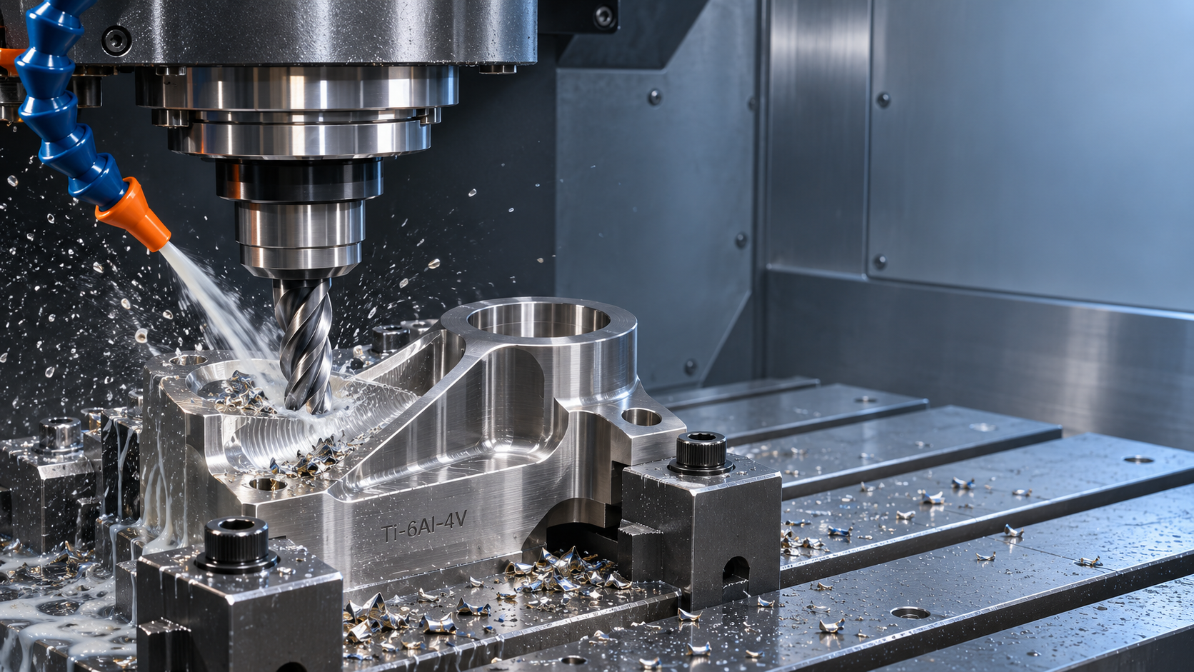
When a titanium milling tool begins to wear quickly or leaves a smeared surface, spindle speed is one of the first settings to check. Calculate the starting RPM from the cutting speed recommended for the specific tool and titanium grade, together with the cutter diameter: RPM = (1,000 × cutting speed in m/min) ÷ (π × cutter diameter in mm). In inch units, use RPM = (12 × cutting speed in surface feet per minute) ÷ (π × diameter in inches).
The calculation gives a starting point, not a guaranteed setting. CNC milling spindle speed for titanium must also suit the tool material, engagement, coolant delivery and rigidity of the setup. Feed must be calculated alongside RPM: changing speed without considering chip load can turn an apparently conservative cut into rubbing.
Calculate RPM from the cutter diameter
Cutting speed describes how fast the cutting edge moves around the cutter’s circumference. RPM describes how many times the spindle turns in a minute. A larger cutter travels farther in one revolution, so it needs fewer revolutions to produce the same cutting speed.
Use the diameter at the cutting edge, not the shank diameter. For a conventional square end mill cutting with its full outside diameter, the nominal cutter diameter is normally the appropriate value. Ball-nose and other contoured tools need additional consideration because their effective cutting diameter depends on where the edge contacts the work.
The two versions of the formula are:
- Metric: RPM = (1,000 × Vc) ÷ (π × D), where Vc is cutting speed in meters per minute and D is diameter in millimeters.
- Inch: RPM = (12 × SFM) ÷ (π × D), where SFM is surface feet per minute and D is diameter in inches.
For a quick shop calculation, π is approximately 3.1416. Keep the units consistent: entering a diameter in inches into the metric equation, or millimeters into the inch equation, produces an unusable result.
Worked metric example
Suppose a tool’s cutting data specifies a starting cutting speed of 60 m/min for the intended titanium operation, and the cutter diameter is 10 mm. This is an illustration of the calculation, not a universal speed recommendation.
RPM = (1,000 × 60) ÷ (3.1416 × 10) = approximately 1,910 RPM.
With a 20 mm cutter at the same 60 m/min, the result is approximately 955 RPM. The diameter doubles, so the RPM is halved. The selected cutting speed remains the same; only the spindle speed needed to achieve it changes.
Worked inch example
For a 0.500-inch cutter and an illustrative cutting speed of 200 SFM:
RPM = (12 × 200) ÷ (3.1416 × 0.500) = approximately 1,528 RPM.
Some shop references use the shortcut RPM ≈ 3.82 × SFM ÷ diameter in inches. It gives essentially the same result when the diameter is entered in inches.

Choose the cutting speed before entering the formula
The arithmetic is straightforward; selecting a suitable cutting speed requires more care. Titanium is not one uniform material, and a value intended for one cutter or operation can be unsuitable for another. Start with the cutting-tool manufacturer’s data for the closest available combination of material, tool and operation. Confirm whether the value assumes a particular coolant method, radial engagement or tool life target.
Check these inputs before accepting a table value:
- Titanium grade and condition: Confirm the alloy and relevant material condition from the job documentation. Do not substitute data for commercially pure titanium when the workpiece is an alloy unless the tool supplier supports that choice.
- Tool material and geometry: Carbide and high-speed steel tools require different cutting data. Coating, flute design and edge preparation also affect the recommended range.
- Operation: Slotting, side milling, finishing and profiling place different demands on the edge. A speed listed for a light radial cut should not automatically be used for a full-width slot.
- Setup: Long tool projection, a thin wall or a less rigid fixture can restrict the usable parameters even when the machine can reach the calculated RPM.
If the tool data gives a range, use a conservative point within the range when engagement or rigidity is uncertain. A conservative starting value is not permission to ignore the rest of the cutting data: feed per tooth, depth of cut and coolant conditions need to remain compatible with the selected speed.
Convert RPM into a usable feed rate
After calculating RPM, determine the programmed table feed from the recommended feed per tooth and the number of effective cutting teeth:
Feed rate = RPM × number of teeth × feed per tooth.
For example, at 1,910 RPM with four effective teeth and an illustrative feed of 0.04 mm per tooth, the calculated feed is 1,910 × 4 × 0.04 = approximately 306 mm/min. The feed-per-tooth value in this example is only for demonstrating the calculation; select the actual value from data appropriate to the tool and cut.
If RPM is reduced from 1,910 to 1,500 while all other inputs remain unchanged, maintaining 0.04 mm per tooth gives 240 mm/min. Leaving the feed at 306 mm/min would instead increase the programmed feed per tooth to about 0.051 mm. Conversely, reducing feed too far without adjusting RPM can make the edge rub rather than cut effectively, increasing heat and encouraging work hardening.
Feed per tooth is not always the same as actual chip thickness. At low radial engagement, chip thinning can require a different feed strategy; tool geometry and the toolmaker’s guidance determine the appropriate correction. Do not apply a compensation factor blindly to a slotting cut or to a tool for which the supplied feed data already accounts for the engagement.
Account for the cut, not just the nominal diameter
Ball-nose tools and effective diameter
At the tip of a ball-nose cutter, the effective cutting diameter approaches zero. A spindle speed calculated from the full nominal diameter therefore overstates the surface speed at a shallow contact point. The effective diameter grows as the contact point moves up the ball.
For a spherical ball end, effective diameter can be estimated as De = 2 × √(2Rh − h²), where R is the ball radius and h is the axial height of the contact point above the tip, in the same units. This geometry assumes contact on the spherical portion; actual contact also depends on surface slope and tool orientation. Use the effective diameter in the RPM formula only when that contact point is known and the resulting speed remains within the toolholder, tool and machine limits.
A very small effective diameter can produce an impractically high calculated RPM. Do not exceed rated limits to achieve the theoretical value. Consider whether the toolpath or tool orientation can move contact away from the center, subject to clearance, finish and programming requirements.
Engagement changes the load
A cutter in a full-width slot generally has less opportunity to clear chips than the same cutter making a light side cut. Recut chips, poor coolant access and high contact time can shorten tool life. Use slotting-specific data where available, and do not assume that reducing RPM alone will compensate for excessive width or depth of cut.
In a narrow radial cut, lower engagement may permit different speeds and feeds, but the cutting edge can rub if the programmed feed does not produce an adequate chip. Corners and toolpath transitions also matter: a programmed side cut may briefly encounter much greater engagement as the tool enters a corner. A toolpath that controls engagement can make the selected cutting data more consistent.
Adjust the starting setting at the machine
Before cutting, verify the programmed tool diameter, spindle direction, work offset and coolant delivery. Check that the holder grips the tool correctly and that projection is no longer than the operation requires. Confirm spindle and toolholder speed ratings; a calculated RPM is not an instruction to exceed either limit.
Run the first cut under controlled conditions, using the machine’s normal safety procedures and guarding. Watch the machine load and listen for changes in cutting sound, but do not rely on either signal alone. Inspect the part and cutting edge when the machine is safely stopped. Compare observations with the expected finish, tool condition and dimensional tolerance.
These symptoms are not unique diagnoses. A worn tool, for example, can cause both poor finish and higher cutting forces even when the original RPM was reasonable. Replace or inspect a damaged tool before attributing every subsequent symptom to spindle speed.
When a change is warranted, alter one parameter at a time where practical and record the setting and observed result. If RPM changes and the intention is to preserve feed per tooth, recalculate feed accordingly. A deliberate feed change may also be appropriate, but it should be treated as a separate decision rather than an accidental consequence of a speed override.
Machine limits and difficult conditions
If the calculated RPM exceeds the machine’s maximum, use no more than the permitted speed and calculate the resulting feed from the chosen feed per tooth. The actual cutting speed will be lower than the selected target. Check whether the toolmaker’s data supports operation at that lower speed; do not assume that a much lower surface speed will behave identically.
At low RPM, available power is not the only limitation. Torque, spindle range, holder security and machine rigidity can constrain a large cutter or heavy cut. An overload at the calculated speed may call for less engagement or a different toolpath, not simply a higher RPM.
For thin walls or long-reach tools, stability may govern the usable speed more than the nominal cutting-speed calculation. A small RPM change can move the cut into or out of a chatter-prone range, but persistent vibration should prompt checks of workholding, tool projection and engagement. If the required material, tool or machine data is unavailable, establish those limits before committing a valuable workpiece to a full cut.
PREVIOUS ARTICLE
NEXT ARTICLE
Recommended for You
 CNC Milling Spindle Speed for Titanium: How to Calculate RPMCNC Machining Technology Center
 How Precise Are Modern CNC Shops? Tolerances and Their LimitsCNC Machining Technology Center
![]() Report: 56% of China's Key Steelmakers Lost Money in SeptemberManufacturing Market Research Center
 Machine Tool Prices: Is a CNC Upgrade Worth the Investment?Manufacturing Market Research Center
![]() China's Official Manufacturing PMI Falls to 49.3 in OctoberManufacturing Market Research Center
 CNC Machine Tool Accuracy Standards Compared: ISO 230 vs. ASME B5.54CNC Machining Technology Center


Aris Katos
Future of Carbide Coatings
15+ years in precision manufacturing systems. Specialized in high-speed milling and aerospace grade alloy processing.
▶
CNC Milling Spindle Speed for Titanium: How to Calculate RPMCNC Machining Technology Center▶
CNC Machine Tool Accuracy Standards Compared: ISO 230 vs. ASME B5.54CNC Machining Technology Center▶
FANUC Links FIELD System Data with Copilot to Advance Shop-Floor Data UseCNC Machining Technology Center▶
Smart Manufacturing for Aerospace: Building Traceability Across CNC OperationsCNC Machining Technology Center▶
Choosing a CNC Machine for Mold Making: Accuracy, Rigidity, and Surface FinishCNC Machining Technology Center
▶
Mastering 5-Axis Workholding Strategies
Join our technical panel on Nov 15th to learn about reducing vibrations in thin-wall components.

Providing you with integrated sanding solutions
Before-sales and after-sales services
Comprehensive technical support