• Global CNC market projected to reach $128B by 2028 • New EU trade regulations for precision tooling components • Aerospace deman
NYSE: CNC +1.2%LME: STEEL -0.4%

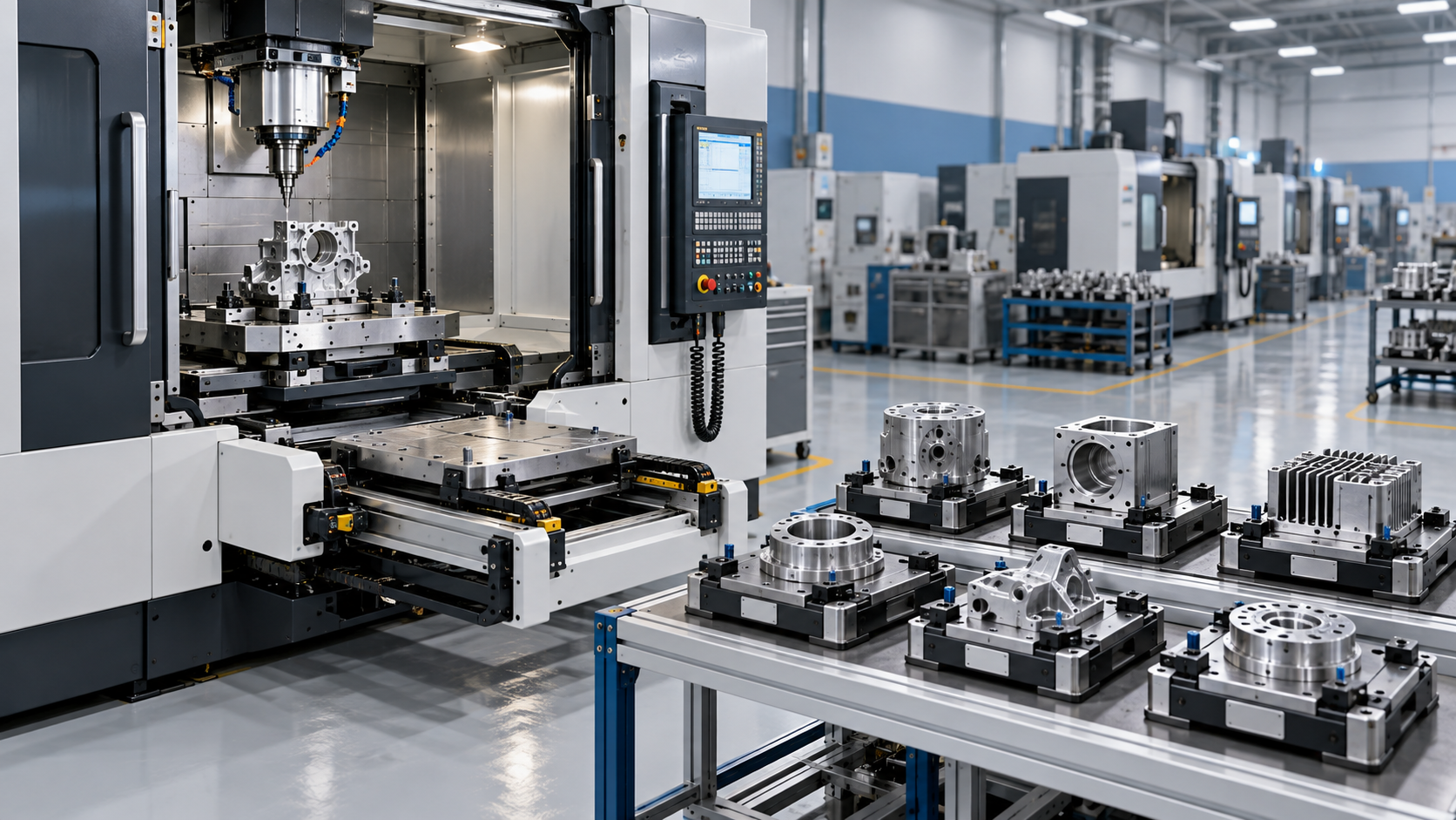
Choosing a CNC Machine for Mold Making: Accuracy, Rigidity, and Surface Finish
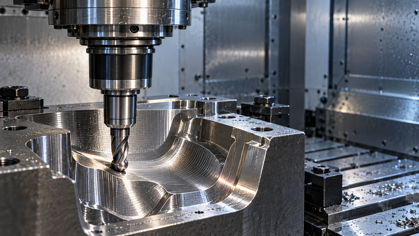
A CNC machine for mold making should be selected by the cavity geometry and surface condition it can sustain during a complete machining cycle—not by its best positioning figure or maximum spindle speed. Accuracy, rigidity, and thermal stability work together. A machine that positions precisely without cutting may still leave dimensional errors, chatter marks, or visible blend lines when machining hardened steel with a long-reach tool.
The decisive comparison is therefore the amount of repeatable, usable mold geometry produced before corrective work is required. A shorter programmed cycle has limited value if it creates additional spotting, polishing, or electrode work. Conversely, a machine optimized for fine finishing may be an inefficient choice for removing large volumes of stock from mold bases.
Define the machining task before comparing machines
“Mold making” covers substantially different cutting conditions. Roughing a large prehardened steel block, finishing a hardened cavity with small ball-nose cutters, and machining an aluminum prototype mold do not place the same demands on the spindle or machine structure.
A useful specification starts with representative parts rather than a general equipment wish list. Record the material and hardness at each machining stage, workpiece mass including fixtures, cavity depth, minimum internal radii, critical tolerances, and required surface texture. Include the longest tool assembly that must reach a functional surface. That assembly can expose a capability limitation hidden by a supplier’s demonstration with short cutters.
Separate requirements that must be achieved directly by milling from those assigned to grinding, electrical discharge machining, or polishing. Sharp internal corners cannot be created by a rotating cutter, and a high-quality milled finish is not automatically suitable for optical or other demanding polished surfaces. The machine should fit the intended process chain rather than be judged against operations it cannot realistically eliminate.
Accuracy must survive motion, load, and temperature
Positioning accuracy describes how closely an axis reaches a commanded location under specified test conditions. Repeatability describes the consistency of returning to a position. Neither, by itself, establishes the accuracy of a three-dimensional cavity.
During contouring, axis straightness, squareness, reversal behavior, servo following error, spindle growth, and cutting deflection all contribute to the finished form. A machine can repeat a location consistently while carrying a systematic geometric error. It can also perform well in individual-axis tests yet generate contour errors when several axes accelerate together.
Compare specifications only when the test method, travel length, compensation state, environmental conditions, and reporting convention are clear. A figure measured over a short central travel is not equivalent to performance across the full working envelope. For large molds, accuracy near the edges of the working area matters as much as accuracy near the table center.
Thermal behavior deserves separate evaluation because mold-finishing cycles can run for many hours. Spindle operation, axis drives, coolant, and ambient temperature changes alter the relative position of the tool and workpiece. A machine that cuts accurately immediately after warm-up may behave differently after extended roughing or a prolonged high-speed finishing pass.
Ask how spindle cooling, structural temperature control, and compensation are implemented, and what operating conditions they require. Compensation can reduce predictable displacement; it cannot remove every transient temperature gradient or correct cutting-force deflection. Acceptance testing should include both stabilized operation and a realistic change in duty cycle.
Rigidity is a property of the complete cutting loop
Machine mass is not a sufficient measure of rigidity. Cutting forces pass through the tool, holder, spindle, head, guideways, frame, table, fixture, and workpiece. Compliance anywhere in that loop can cause dimensional error or unstable cutting.
Structural layout matters because stiffness changes with axis position and component extension. A head positioned far from its supports or a heavily loaded table near its travel limit may behave differently from the same machine in a favorable central position. Compare performance at the locations and loads the mold will actually require.
Guideway type also needs context. Box ways, rolling-element guides, and other arrangements offer different combinations of damping, friction, speed, and maintenance requirements. No guideway label proves that a machine will deliver superior mold surfaces. Assembly quality, structural proportions, spindle behavior, and motion tuning remain decisive.
Deep cavities make tool rigidity especially important. In a simplified cantilever model, deflection increases strongly with unsupported tool length; shortening reach can therefore deliver a larger benefit than a modest improvement in machine stiffness. Holder clearance, spindle-nose access, and fixture height should be checked together before specifying axis travels.
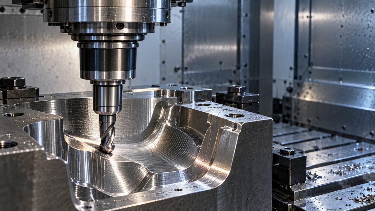
A collision-free toolpath is not necessarily a productive one. If access requires an unusually slender cutter or excessive holder extension, the practical result may be reduced engagement, slower feeds, and increased vibration. Evaluate reach using the complete spindle–holder–tool assembly, not the cutting tool alone.
Match spindle capability to cutter size and material
Maximum spindle speed is relevant when small cutters require high rotational speed to achieve an appropriate cutting speed. It says little about the torque available for larger tools, the spindle’s continuous operating capability, or its behavior under load.
Review the power and torque curves across the intended operating range. Distinguish continuous ratings from short-duration ratings. A high-speed spindle selected for fine cavity finishing may lack the low-speed torque needed for aggressive roughing with larger cutters. Where both operations are substantial, separating roughing and finishing between machines can be more effective than forcing one spindle to cover incompatible priorities.
Spindle interface and holder selection also affect the result. Taper contact, clamping condition, holder balance, tool projection, and runout all influence cutting stability. With small tools, runout creates unequal tooth loading and can impair both tool life and surface consistency. A spindle accuracy figure measured at the nose does not establish runout at the cutting edge of an assembled tool.
For hardened steel, evaluate the spindle, tooling, and cutting strategy as a system. Stable light engagement with a short tool can be more useful than nominal power. For aluminum, chip evacuation and resistance to chip recutting may become the limiting conditions. Coolant delivery, air supply, filtration, and enclosure design should support the intended process rather than appear merely as accessory options.
Surface finish depends on more than a roughness value
Surface roughness, waviness, and form error describe different aspects of a mold surface. A low roughness reading over a short trace can coexist with visible bands or broader contour deviations. Those defects may require substantial polishing even when the reported roughness meets the drawing requirement.
For ball-nose finishing, stepover sets the theoretical scallop height, but actual texture also depends on local curvature, tool orientation, effective cutting diameter, runout, vibration, and tool wear. Near the center of a ball-nose cutter, cutting speed approaches zero. Reaching a surface is therefore not the same as cutting it under favorable conditions.
The control must preserve contour quality while processing the toolpath. Look-ahead, acceleration limits, jerk management, interpolation, and smoothing settings influence how the axes negotiate short segments and changing curvature. A high programmed feed may never be reached on a finely segmented three-dimensional path. Aggressive smoothing may improve motion while moving the tool away from the intended contour if its tolerance is set too loosely.
Evaluate the complete CAD/CAM-to-machine chain. CAM chordal tolerance, postprocessor output, control settings, and machine dynamics must be compatible. Comparing machines using different path tolerances or finishing allowances can produce misleading conclusions about both speed and quality.
Polishing allowance also needs discipline. Extra stock is not a harmless reserve when polishing can alter shutoff faces, parting edges, small radii, or cavity dimensions. The relevant question is whether the milled surface can reach its final condition without losing critical geometry.
Choose additional axes for access, not prestige
A three-axis machining center remains a valid choice when cavity access is straightforward and short tools can reach the required surfaces. Additional rotary axes become valuable when they reduce setups, improve tool orientation, or allow shorter tools around steep walls and complex features.
Indexed five-axis machining can provide much of that access benefit without requiring simultaneous five-axis motion throughout the cut. Simultaneous machining adds flexibility, but also introduces rotary-axis accuracy, pivot calibration, tool-center-point control, and postprocessor requirements.
For large or heavy molds, check rotary-axis load limits, workpiece inertia, usable envelope, and interference—not just the table’s nominal load capacity. A tilted workpiece can consume clearance rapidly. A head-based configuration avoids rotating the full workpiece, but its head geometry and angular stiffness still require evaluation.
Additional axes are justified when the resulting tool access or setup reduction outweighs the added calibration and process complexity. They do not compensate for inadequate thermal stability or weak spindle performance.
Make the acceptance cut expose the likely failure modes
A supplier demonstration should resemble the difficult parts of production, not simply produce an attractive sample. Use representative material, hardness, tool reach, fixturing, and cutting conditions. Include a deep region, a steep wall, a shallow curved surface, and a blend between machining areas if those features occur in the intended work.
The test should establish more than whether a single part passes inspection:
- Geometry: Measure critical dimensions and freeform deviations, including locations across the required working envelope.
- Surface condition: Assess roughness, waviness, visible tool marks, and transitions between passes or setups.
- Thermal consistency: Repeat selected features or measurements after representative operating periods.
- Tooling sensitivity: Use the production-relevant holder and reach, and document tool condition.
- Time to an acceptable result: Record machining, tool changes, probing, interruptions, and corrective finishing separately.
Agree on the measurement method and environmental conditions before cutting. On-machine probing is useful for setup and process control, but it is not fully independent verification because some machine errors can affect both machining and probing. Use suitable external measurement for acceptance, with uncertainty small enough to support the tolerance being assessed.
Keep the test configuration documented: compensation settings, warm-up routine, control options, CAM parameters, coolant conditions, and fixture arrangement. Otherwise, a successful demonstration may depend on conditions that are difficult to reproduce after installation.
The strongest choice is the machine that meets the required geometry and surface condition repeatedly with a sustainable process window. When two machines both satisfy that requirement, compare their total time to an accepted mold—not just cutting time—and the effort needed to maintain that capability. This makes accuracy, rigidity, and finish measurable production outcomes rather than isolated specification-sheet claims.
NEXT ARTICLE
Recommended for You
![]() Mitsubishi Electric Announces Physical AI System Linking Humanoid Robots and CNC MachinesMachine Tool Industry Editorial Team
 Precision Machining for Defense: Supplier Quality and Traceability ChecksManufacturing Market Research Center
![]() Nidec Machine Tool Launches MVR-5X Five-Axis Gantry MachineMachine Tool Industry Editorial Team
 Choosing a Precision Disc Parts Manufacturer in China: Tolerances and Quality ChecksManufacturing Market Research Center
![]() Siemens Executive Says AI Could Raise Factory Automation to 80%Manufacturing Market Research Center
 Choosing Automated Machine Tools for High-Mix, Low-Volume ProductionMachine Tool Industry Editorial Team


Aris Katos
Future of Carbide Coatings
15+ years in precision manufacturing systems. Specialized in high-speed milling and aerospace grade alloy processing.
▶
Choosing a CNC Machine for Mold Making: Accuracy, Rigidity, and Surface FinishCNC Machining Technology Center▶
How to Cut CNC Machining Energy Use per Part Without Longer Cycle TimesCNC Machining Technology Center▶
Will a Mazak CNC retrofit work with your existing servo drives?CNC Machining Technology Center▶
Do energy-efficient machine tools reduce power use at partial load?CNC Machining Technology Center▶
Comparing energy-efficient machine tools by energy use per partCNC Machining Technology Center
▶
Mastering 5-Axis Workholding Strategies
Join our technical panel on Nov 15th to learn about reducing vibrations in thin-wall components.

Providing you with integrated sanding solutions
Before-sales and after-sales services
Comprehensive technical support