• Global CNC market projected to reach $128B by 2028 • New EU trade regulations for precision tooling components • Aerospace deman
NYSE: CNC +1.2%LME: STEEL -0.4%

How Precise Are Modern CNC Shops? Tolerances and Their Limits
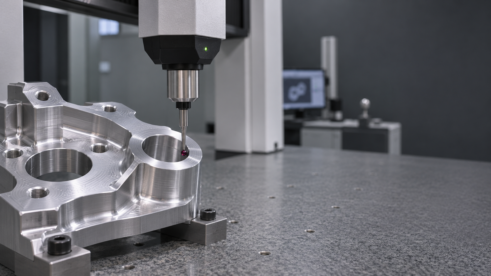
How precise is precision engineering in modern CNC shops, and what limits achievable tolerances? The answer depends on more than machine specifications. Material behavior, thermal stability, tooling, fixturing, and measurement methods all influence whether a shop can produce parts consistently within tolerance. A machine may position an axis with exceptional repeatability, yet the finished component can still fail a bore, flatness, or positional requirement. For a technical evaluator, the question is not simply what a machine can do once, but what the complete manufacturing and inspection process can deliver over time.
Tolerance is a requirement, not a measure of machine quality
A tolerance defines the permitted variation in a specified characteristic. A diameter of 20.00 mm with a tolerance of ±0.02 mm, for example, permits sizes from 19.98 mm to 20.02 mm. That says nothing by itself about whether the bore is straight, round, correctly positioned, or aligned with another feature. Those requirements must be defined separately when they matter to the part’s function.
This distinction becomes important when comparing supplier claims. “Precision to ±0.01 mm” may refer to a favorable feature on a small part, rather than every dimension on a complex component. It may also describe a machine’s positioning performance rather than the accuracy of a machined workpiece. Ask what was measured, over what travel or feature size, under which conditions, and whether the figure represents a single result or sustained production.
Accuracy describes closeness to a reference value; repeatability describes the consistency of repeated results under stated conditions. A process can be repeatable but consistently offset, in which case a correction may bring it closer to target. A process that wanders unpredictably is harder to control, even if an occasional part measures almost exactly on nominal.
What tolerance ranges mean in practice
General-purpose CNC milling and turning can often produce features within a few hundredths of a millimeter when the geometry, material, setup, and inspection method are suitable. Tolerances in the low micrometers may be achievable for selected features with a controlled process, but they should not be treated as a routine promise for an entire component. Large parts, deep bores, thin walls, and long distances between related features can change the picture considerably.
A turned bearing seat on a rigid shaft is not equivalent to a similar-sized bore deep inside a thin-walled housing. The first may be accessible to a stable cutting and gauging arrangement; the second may be affected by tool reach, interrupted cuts, clamping distortion, and restricted measurement access. Even within the same drawing, one feature may need finishing by grinding or honing while others remain economically machinable on a standard machining center.
Surface finish is another separate requirement. A tight dimensional tolerance does not automatically produce a suitable surface for sealing, fatigue performance, or bearing contact. Specify the relevant surface texture parameter and any functional requirements rather than assuming a small size tolerance covers them.
Where precision is lost between the program and the part
The programmed toolpath is only one element in a chain that includes the machine structure, cutting tool, workholding, material, environment, and inspection system. Errors can accumulate or partially offset one another. Because their effects vary with geometry and operating conditions, adding a machine specification to a tooling specification is rarely a reliable way to predict the final part.
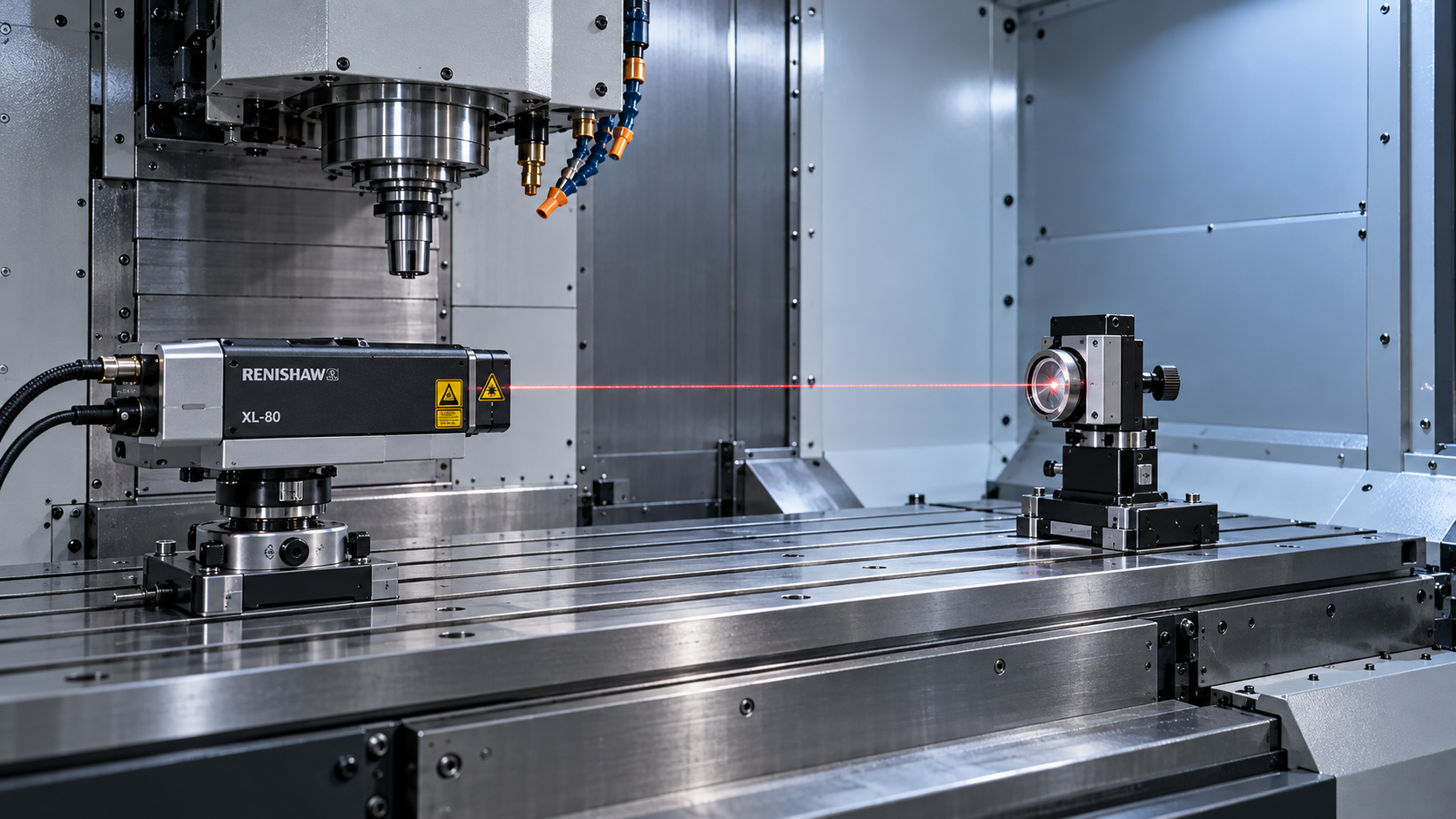
Temperature deserves particular attention. The spindle, ball screws, coolant, cutting zone, fixture, and workpiece can all change temperature during production. Warm-up behavior may differ from a machine that has been running for several hours, and a part measured immediately after machining may not have reached the same temperature as the inspection room. For tight work, evaluators should ask how the shop handles warm-up, coolant control, part stabilization, and compensation across a shift—not just whether the building is air-conditioned.
Workholding can be just as consequential. Clamping a thin ring too firmly may distort it during cutting; once released, the measured shape can change. A long shaft can deflect under cutting force, while a deep pocket can allow previously balanced material stresses to move the part. The practical response may involve softer clamping, additional support, roughing before a stabilization period, or a revised machining sequence. None of those adjustments is visible in an axis-positioning specification.
Tool wear and cutting forces add another source of drift. A process that holds size at the start of a batch may move toward a limit as the edge wears. A credible control plan identifies how offsets, tool life, probing, and inspection frequency are managed. It also explains what happens when a trend approaches a limit, rather than relying solely on a final inspection to find nonconforming parts.
Geometric controls make the requirement functional
A drawing can contain individually acceptable dimensions and still allow a part that will not assemble. Consider a disc with a central locating bore and a bolt pattern: hole diameters alone do not establish whether the pattern is correctly located relative to the bore. A positional tolerance tied to appropriate datums expresses that relationship more directly.
Geometric dimensioning and tolerancing systems, including ASME Y14.5 and the ISO geometrical product specifications system, provide frameworks for defining such requirements. They are not interchangeable by assumption. The drawing should identify the applicable standard and edition, and the supplier should understand how its datum references, modifiers, and acceptance criteria are to be interpreted.
Datum selection also has a manufacturing consequence. If the functional datum surfaces are difficult to access or unstable when clamped, the shop may need a second setup or a dedicated fixture. That introduces additional opportunities for alignment error. Five-axis machining can reduce the number of setups for some geometries, but it does not eliminate rotary-axis errors, calibration needs, tool deflection, or the need to verify relationships between features.
Inspection capability is part of manufacturing capability
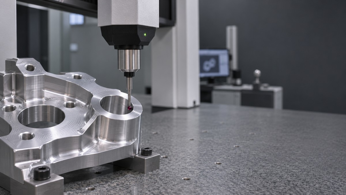
A tolerance is useful only if the parties can agree how to assess it. Coordinate measuring machines, bore gauges, air gauges, optical systems, and on-machine probes each have strengths and limitations. A probe on the machine is valuable for setup and process control, but an independent measurement may still be required when the acceptance plan calls for it. The machine and its probe can also share sources of error.
For a critical feature, ask for the measurement method, calibration traceability, sampling plan, environmental controls, and treatment of measurement uncertainty. A gauge reading close to a specification limit does not by itself establish an unambiguous pass or fail: the agreed decision rule determines how uncertainty is considered. ISO 14253-1 addresses decision rules for proving conformity or nonconformity in geometrical product specifications; its use and any contractual alternatives should be agreed for the project.
Sampling matters as well. A first-article report can demonstrate that a process produced an acceptable part at one point in time. It does not, on its own, demonstrate capability over a production run. For a stable, suitably characterized process, capability indices such as Cp and Cpk can help assess variation against specification limits. Their interpretation depends on the data, measurement system, distribution assumptions, and sampling strategy; a number without that context is a weak basis for approval.
How to evaluate a shop beyond its equipment list
A useful technical discussion starts with the actual drawing and operating conditions. Rather than asking for a universal tolerance, identify the features that govern fit, alignment, sealing, or motion. Then ask the shop to explain its proposed process for those features, including how they will be located, finished, measured, and protected during handling.
- Compare like with like: Request evidence for similar materials, feature sizes, geometries, and production quantities. A small trial component is not a substitute for a large structural part.
- Examine the setup strategy: Identify which critical relationships are produced in one clamping and which depend on re-registration between operations.
- Review the control plan: Check tool-change triggers, in-process checks, reaction limits, and how nonconforming material is segregated.
- Check the measurement plan: Confirm datum simulation, gauge access, uncertainty, reporting format, and the agreed acceptance decision rule.
- Account for downstream processes: Heat treatment, coating, deburring, cleaning, and assembly can alter or affect the final verified condition.
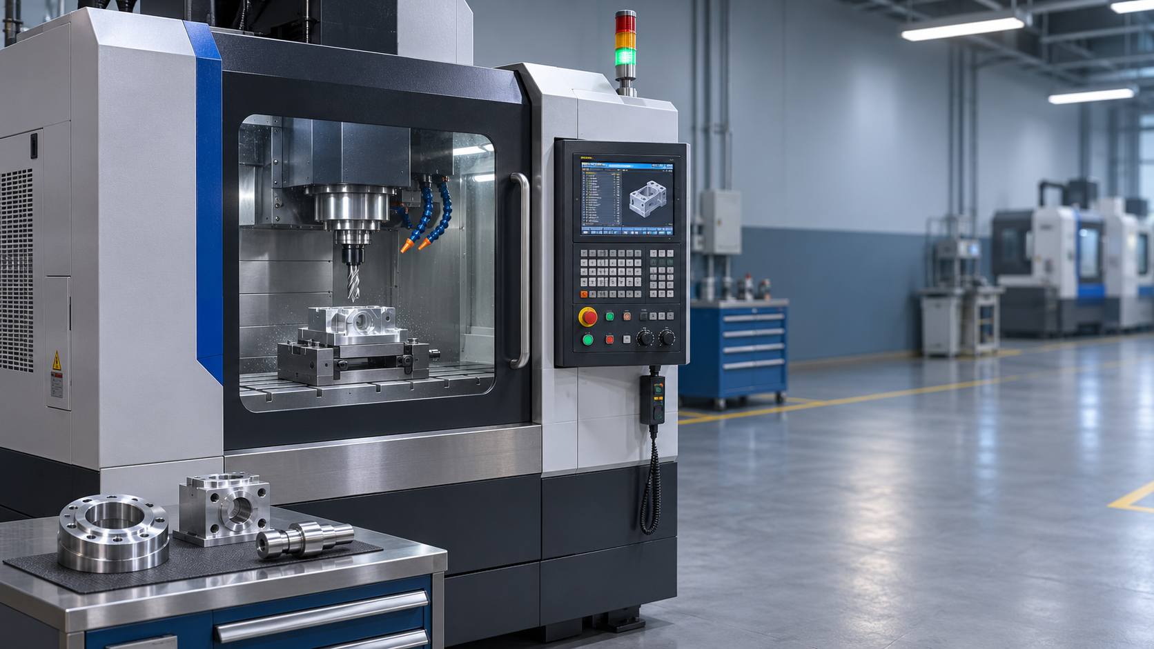
Automation and digital monitoring can make a process more consistent, particularly when tool offsets and inspection results feed a disciplined control loop. They do not automatically correct a poor fixture or an unclear drawing. Equally, a machine tool built in a well-established manufacturing region is not proof of a specific shop’s capability; installation, maintenance, programming, and local process control still determine the result.
Tighter is not always better
Every unnecessary reduction in tolerance can narrow the available process window. It may require additional finishing, more frequent inspection, temperature control, specialized gauges, or a higher risk of scrap. On a complex assembly, those costs can accumulate without improving performance if the controlled feature does not affect the functional requirement.
The more effective approach is selective precision: apply tight limits where the design needs them and allow appropriate variation elsewhere. Before approving a manufacturing route, confirm the functional datums, the condition in which each feature is accepted, the required production quantity, and the evidence expected for ongoing control. Those details are more useful than a single precision claim—and much more likely to reveal whether the proposed process can actually deliver.
PREVIOUS ARTICLE
NEXT ARTICLE
Recommended for You
 How Precise Are Modern CNC Shops? Tolerances and Their LimitsCNC Machining Technology Center
![]() Report: 56% of China's Key Steelmakers Lost Money in SeptemberManufacturing Market Research Center
 Machine Tool Prices: Is a CNC Upgrade Worth the Investment?Manufacturing Market Research Center
![]() China's Official Manufacturing PMI Falls to 49.3 in OctoberManufacturing Market Research Center
 CNC Machine Tool Accuracy Standards Compared: ISO 230 vs. ASME B5.54CNC Machining Technology Center
![]() Li Daokui: China Overtakes Germany With 21.6% of Global Machine Tool ExportsGlobal Machine Tool Trade Research Center


Aris Katos
Future of Carbide Coatings
15+ years in precision manufacturing systems. Specialized in high-speed milling and aerospace grade alloy processing.
▶
How Precise Are Modern CNC Shops? Tolerances and Their LimitsCNC Machining Technology Center▶
How thermal drift affects accuracy in high-precision manufacturingCNC Machining Technology Center▶
What Tolerances Are Typical in Precision Machining?CNC Machining Technology Center▶
Industrial Machining: Selecting Processes for Tight-Tolerance Metal PartsCNC Machining Technology Center▶
How Does Precision Machining Differ From Standard Machining?CNC Machining Technology Center
▶
Mastering 5-Axis Workholding Strategies
Join our technical panel on Nov 15th to learn about reducing vibrations in thin-wall components.

Providing you with integrated sanding solutions
Before-sales and after-sales services
Comprehensive technical support