• Global CNC market projected to reach $128B by 2028 • New EU trade regulations for precision tooling components • Aerospace deman
NYSE: CNC +1.2%LME: STEEL -0.4%

CNC Machine Tool Accuracy Standards Compared: ISO 230 vs. ASME B5.54
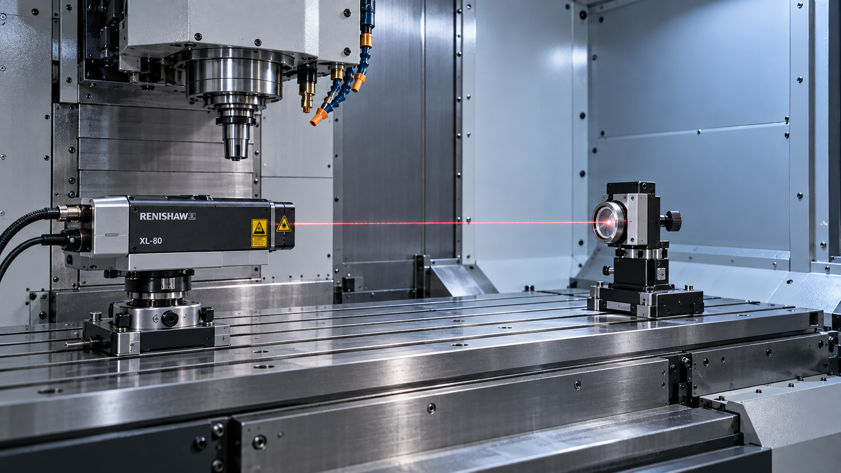
A CNC machine’s stated positioning accuracy cannot be compared reliably from a single number. ISO 230 is a series of test-code standards covering different aspects of machine tool performance, while ASME B5.54 addresses the performance evaluation of machining centers. The distinction matters: two specifications can describe the same axis in micrometers yet represent different test sequences, statistical treatments, travel ranges or environmental conditions.
Neither standard, by itself, establishes a universal pass/fail accuracy limit or guarantees the tolerance of a finished component. A meaningful CNC machine tool accuracy standards comparison starts with the applicable edition, the specific test, the reported parameter and the conditions under which the result was obtained.
What each standard covers
ISO 230 is a family of standards rather than one complete accuracy test. Its parts address different machine characteristics and measurement methods. For example, ISO 230-1 concerns geometric accuracy under no-load or quasi-static conditions; ISO 230-2 addresses positioning accuracy and repeatability of numerically controlled axes; ISO 230-3 covers thermal effects; and ISO 230-4 addresses circular tests for numerically controlled machine tools. Other parts address additional tests and measurement topics.
ASME B5.54, Methods for Performance Evaluation of Computer Numerically Controlled Machining Centers, provides methods for evaluating machining-center performance. Its scope includes a range of geometric, positioning and other performance tests relevant to that machine category. It should not be treated as a general-purpose standard for every CNC machine configuration: a turning center, for example, may require other applicable standards and tests.
This is therefore not a simple choice between two equivalent documents. A specification citing “ISO 230” without a part number leaves the test method unclear. A specification citing ASME B5.54 without identifying the test and edition can also leave important details unresolved. In both cases, the machine-specific standard and the purchase agreement may determine which tests are required and what limits apply.
Positioning accuracy: why the headline numbers differ
Axis positioning tests compare commanded positions with measured positions. The resulting errors show how closely an axis reaches selected targets and how consistently it returns to them. That basic principle is common to both approaches, but the test plan and the way the measurements are reduced to reported values matter as much as the instrument used.
ISO 230-2 defines positioning accuracy and repeatability parameters based on repeated measurements at target positions. Its reporting distinguishes behavior associated with direction of approach as well as variation among repeated approaches. A result labelled with an ISO parameter should be interpreted according to the definition in the specified edition, not as a generic synonym for “maximum observed error.”
ASME B5.54 also provides procedures for evaluating positioning performance, but a reported B5.54 result must be read using that standard’s applicable definitions and procedure. It is unsafe to assume that an ISO positioning accuracy value and an ASME positioning accuracy value represent identical statistical quantities simply because both are expressed in the same unit.
The difference becomes important when comparing quotations. One supplier might report a value for the full axis travel, while another reports a value over a shorter measuring length. One might include approaches from both directions, while another highlights a unidirectional result. A shorter range or a different approach strategy can change the result without any change in the machine’s underlying construction.
Accuracy and repeatability should also remain separate. A machine can return consistently to a position that is offset from the command: repeatability may be good even when positioning error is significant. Conversely, a corrected axis can have a small average positioning error while showing greater variation between repeated approaches. Both behaviors matter when judging whether the machine can hold a feature’s location across a production run.
Test conditions that can change the comparison
Measurement range and target layout
A positioning value is meaningful only in relation to the tested travel and target positions. Full-stroke measurements expose error patterns that may not appear in a short segment; a localized test can be useful for a part family concentrated in one region of the work envelope. Neither result automatically describes every position on the axis.
The number and distribution of targets, number of repeated approaches, dwell time and approach direction should be available in the report. These details determine what the test sampled and how its reported result was calculated. Do not convert a full-travel result into an assumed short-travel result by simple proportional scaling: positioning errors need not vary linearly along the axis.
Compensation and machine configuration
Modern controls can apply positioning and other compensation. A compensated result can be entirely valid, but the report should identify the compensation state and any relevant calibration conditions. If the production machine will operate with compensation enabled, testing in that state can support the intended use; if compensation settings may change after installation or service, their control becomes part of maintaining the result.
Configuration also matters. Record the spindle orientation where relevant, the position of other axes, the table or pallet arrangement, and any installed accessories or load. The measured relationship between tool and workpiece can change with axis position and structural loading, even when the same linear axis is being tested.
Temperature and stabilization
Thermal expansion and deformation can alter measured positions during a test. Ambient temperature, machine warm-up, spindle operation and heat generated by axis motion all affect the measurement context. An axis measured on a stabilized machine at one thermal state is not necessarily comparable with the same axis measured immediately after a different operating cycle.
ISO 230-3 addresses thermal effects, but a thermal test and a positioning test answer different questions. A positioning report taken under controlled conditions does not, by itself, describe how the machine behaves during a long spindle cycle or after changing cutting conditions. If the intended process is sensitive to thermal drift, define a separate test or operating-cycle requirement rather than assuming it is covered by the positioning number.
Measurement uncertainty
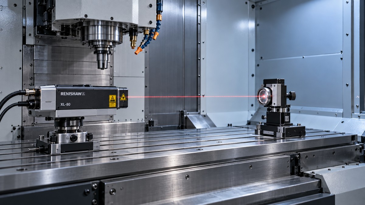
Laser interferometers and other calibrated instruments do not eliminate measurement uncertainty. Instrument calibration, alignment, environmental compensation, setup geometry and data processing all contribute to it. A report should identify the equipment and traceability and, where required by the agreement, provide an uncertainty statement or the information needed to evaluate it.
This matters most when a result is close to an acceptance limit. Before testing, the parties should agree not only on the limit but also on the decision rule: how measurement uncertainty will be considered when determining conformity. Without that agreement, the same measured value can lead to different acceptance decisions.
Geometric and contouring tests answer different questions
Positioning accuracy is only one part of machine performance. Straightness, squareness, spindle-related errors and other geometric deviations influence the relative position and orientation of the cutting tool and workpiece. A machine can meet a linear positioning criterion and still produce unacceptable geometry if another error source dominates the operation.
Geometric tests are also sensitive to where and how they are performed. Squareness measured between two axes is not a complete description of volumetric error throughout the work envelope. For a large structural component, the locations of the features and the axis positions used to machine them may matter more than an isolated geometric value measured near the center of travel.
Circular interpolation tests add a different perspective. In a circular test, two axes coordinate to follow a programmed path, and the measured trajectory can reveal combined effects associated with motion, control settings and machine mechanics. ISO 230-4 addresses circular testing of numerically controlled machine tools; the specific test conditions and analysis method remain essential to interpretation.
A circularity plot is not a complete diagnostic on its own. A visible deviation near an axis reversal, for example, calls for investigation, but the plot alone should not be used to assign a unique cause without supporting measurements. Feed rate, radius, machine state and test setup should accompany the result. Equally, a favorable circular test does not establish performance for every contour, feed rate or three-dimensional tool path.
Building a comparable acceptance specification
The strongest comparison begins before the machine is ordered, when the test plan can be matched to the features that matter. A bore-spacing requirement may justify particular attention to axis positioning and thermal stability. A part with perpendicular mounting faces may make axis squareness and workholding effects more consequential. A contouring requirement may need an interpolation test at a representative feed rate, rather than reliance on static axis specifications alone.
A usable acceptance document should identify:
- The standard and edition: include the ISO 230 part or the applicable ASME B5.54 edition, plus any machine-specific standard referenced.
- The machine and test configuration: identify the axes, tested travel, relevant positions of other axes, load, accessories and compensation state.
- The procedure and reported quantity: state the test, approach directions, measurement locations, repetitions and the exact parameter to be reported.
- The operating and environmental conditions: define relevant temperature conditions, warm-up, spindle state and stabilization requirements.
- The acceptance criterion: specify a numerical limit, unit and decision rule rather than relying on a statement that the machine is “tested to” a standard.
- The evidence: require a report identifying the measurement equipment, calibration traceability, results, conditions and any deviations from the agreed procedure.
Factory testing and installation-site testing should not automatically be treated as interchangeable. Transportation, foundation, leveling, utilities and the local thermal environment can change the conditions under which a machine operates. If both tests are required, the agreement should specify which checks will be repeated, how the site will be prepared and which limits apply at each location.
A supplier’s statement of compliance with a test method is also not the same as independent certification. It may mean that measurements were performed using the cited procedure; it does not necessarily mean an external body certified the machine or that the machine met a separately defined tolerance. The test report, acceptance criteria and any independent assessment should be requested as distinct evidence.
When the available results use different standards
Do not rank machines solely by choosing the smaller published accuracy figure. Ask whether the figures refer to the same axis, travel, measurement direction, parameter, compensation state and thermal condition. Then examine whether the underlying measurements and calculations permit a defensible comparison under the specified editions.
If the reports use materially different procedures or omit essential conditions, a numerical conversion between ISO 230-2 and ASME B5.54 results should not be assumed. A common, agreed test on the machines—or a standardized test plan for the pending purchase—is more useful than applying an unsupported conversion factor.
The practical choice is therefore not that ISO is inherently stricter or ASME inherently more representative. The relevant question is whether the selected tests expose the errors that can affect the intended process, and whether the resulting evidence is comparable under documented conditions. A standard provides the measurement framework; the acceptance specification connects that framework to the machine’s required performance.
NEXT ARTICLE
Recommended for You
![]() China's Official Manufacturing PMI Falls to 49.3 in OctoberManufacturing Market Research Center
 CNC Machine Tool Accuracy Standards Compared: ISO 230 vs. ASME B5.54CNC Machining Technology Center
![]() Li Daokui: China Overtakes Germany With 21.6% of Global Machine Tool ExportsGlobal Machine Tool Trade Research Center
 Machine Tool Prices: What to Budget Beyond the Purchase PriceGlobal Machine Tool Trade Research Center
![]() Survey: 81% Expect US Cutting Tool Shipments to Rise or Hold Steady in 2026Machine Tool Industry Editorial Team
 CNC Fixture Design: Locating and Clamping for Accurate MachiningCNC Machining Technology Center


Aris Katos
Future of Carbide Coatings
15+ years in precision manufacturing systems. Specialized in high-speed milling and aerospace grade alloy processing.
▶
CNC Machine Tool Accuracy Standards Compared: ISO 230 vs. ASME B5.54CNC Machining Technology Center▶
FANUC Links FIELD System Data with Copilot to Advance Shop-Floor Data UseCNC Machining Technology Center▶
Smart Manufacturing for Aerospace: Building Traceability Across CNC OperationsCNC Machining Technology Center▶
Choosing a CNC Machine for Mold Making: Accuracy, Rigidity, and Surface FinishCNC Machining Technology Center▶
How to Cut CNC Machining Energy Use per Part Without Longer Cycle TimesCNC Machining Technology Center
▶
Mastering 5-Axis Workholding Strategies
Join our technical panel on Nov 15th to learn about reducing vibrations in thin-wall components.

Providing you with integrated sanding solutions
Before-sales and after-sales services
Comprehensive technical support