• Global CNC market projected to reach $128B by 2028 • New EU trade regulations for precision tooling components • Aerospace deman
NYSE: CNC +1.2%LME: STEEL -0.4%

Industrial Machining: Selecting Processes for Tight-Tolerance Metal Parts
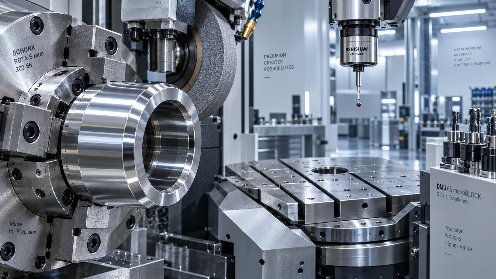
A drawing may specify a bore within a few microns, a perpendicularity requirement that must hold after heat treatment, and a surface finish that affects sealing or fatigue life. On paper, those requirements occupy only a few lines. In production, they determine nearly every important decision: the machine configuration, workholding method, cutting sequence, inspection plan, and whether the part should be milled, turned, ground, wire-cut, or machined in a combined process.
For technical evaluators, selecting an industrial machining route for tight-tolerance metal parts is not simply a matter of choosing the most accurate machine available. The strongest process is usually the one that controls variation across the full manufacturing chain while remaining practical for the intended volume, material, and geometry. A highly capable process can still be the wrong choice if it creates unnecessary setups, unstable clamping, excessive cycle time, or difficult-to-measure features.
This guide examines how to assess CNC turning, milling, grinding, EDM, and multi-axis machining when dimensional precision, geometric control, and reliable repeatability matter.
Start with the functional requirement, not the machine name
Parts are often routed toward a process because of familiar geometry: shafts go to lathes, housings go to machining centers, and hard parts go to grinders. That is a useful starting point, but it is not a complete selection method. The more reliable question is: which surfaces control the part’s function, and how are those surfaces related to one another?
A hydraulic spool, for example, may depend on the relationship between diameter, cylindricity, straightness, and surface texture. A turbine bracket may be less sensitive to nominal dimensions than to positional accuracy between angled holes and machined mounting faces. A mold insert may require fine internal corners and features that cannot tolerate cutting-tool access limitations. Each situation points to a different industrial machining strategy.
Before comparing equipment, identify the characteristics that truly drive performance:
- Critical dimensions: nominal size, tolerance band, and whether the feature is external, internal, deep, interrupted, or difficult to access.
- Geometric tolerances: concentricity, runout, flatness, profile, perpendicularity, and true position often matter more than a single linear tolerance.
- Surface integrity: roughness, waviness, burr condition, residual stress, recast layer risk, and the need to preserve fatigue performance.
- Material condition: annealed, pre-hardened, heat-treated, coated, or prone to distortion during machining.
- Datum strategy: whether key features can be produced and inspected from stable, repeatable references.
- Production demand: prototype quantity, recurring batch size, annual volume, and the expected frequency of design changes.
When these factors are clear, the process discussion becomes more disciplined. Rather than asking whether a five-axis machining center is “better” than a three-axis system, evaluators can ask whether simultaneous access, fewer reclamps, or improved tool orientation will reduce the specific risks embedded in the part drawing.
What each core machining process does best
CNC turning: the natural choice for rotational accuracy
CNC turning remains the primary route for shafts, sleeves, pins, bushings, flanges, and other parts organized around a rotational centerline. When external diameters, internal bores, faces, and grooves must remain concentric, turning can establish those relationships in one clamping. This is especially valuable where runout or coaxiality directly affects bearing fits, seals, rotating assemblies, or fluid control.
Modern turning centers may include live tooling, Y-axis capability, sub-spindles, and automatic bar feeding. These features expand the practical scope of a lathe, allowing cross holes, flats, keyways, and secondary milling operations to be completed without moving the part to a separate machine. For medium- to high-volume work, that reduction in handling can improve consistency as much as it improves throughput.
Turning is not automatically the final operation for every cylindrical surface. Fine boring may be required for an internal feature, while a hardened journal or precision sealing diameter may need cylindrical grinding after heat treatment. Long, slender workpieces also demand attention to support methods, deflection, and vibration; a nominally accurate lathe cannot compensate for poor process stability.
CNC milling: flexibility for prismatic and multi-feature parts
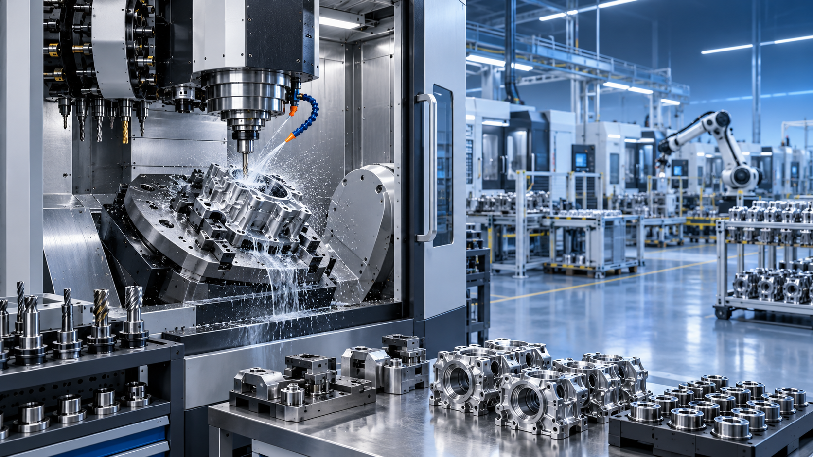
For plates, brackets, valve bodies, structural components, manifolds, and complex housings, CNC milling offers broad geometric flexibility. Face milling establishes reference planes, while end milling, drilling, reaming, boring, and thread milling can create a large number of features from a common datum system.
A three-axis machining center is often sufficient for parts with accessible top and side features, particularly when fixture design allows multiple orientations. However, every repositioning introduces an opportunity for datum transfer error. If a precision hole pattern must be tightly related to features on several faces, the apparent savings of a simpler setup can disappear in alignment checks, rework, and inspection effort.
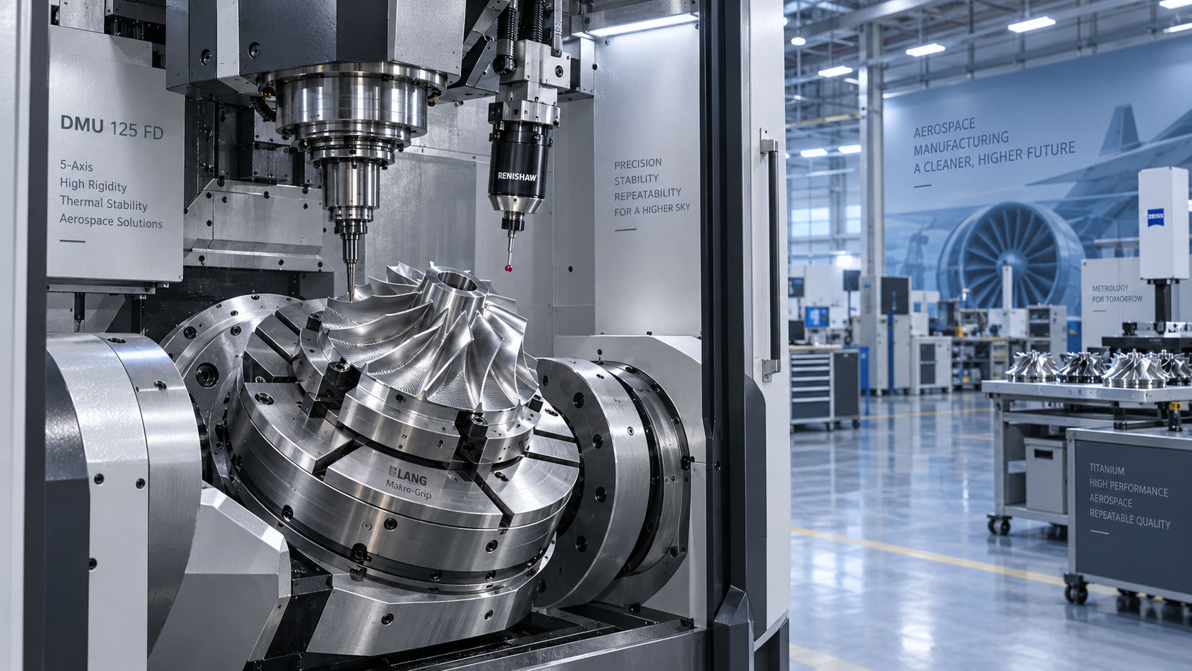
Four-axis indexing can reduce those risks for parts that need repeatable access around a cylindrical or rectangular form. Five-axis machining becomes more compelling when feature angles are compound, tool access is restricted, wall thickness varies, or the part would otherwise require several fixtures. The value is not merely “more axes.” It is the ability to finish related surfaces with fewer interruptions to the part’s coordinate system.
Grinding: when the tolerance is only part of the story
Grinding is often selected late in the route because it can hold very fine size control and produce surfaces beyond the practical finish of conventional cutting. Yet its most important contribution is frequently stability after heat treatment. Hardened steels, precision bearing components, transmission parts, dies, and high-wear interfaces may distort during thermal processing. Grinding restores the final geometry after that movement has occurred.
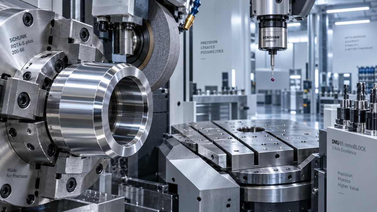
Surface grinding is suited to flatness and parallelism on plates, guides, and precision tool components. Cylindrical grinding addresses external diameters and journals, while internal grinding supports highly accurate bores. Centerless grinding is particularly effective for high-volume cylindrical parts where consistent outside diameter and efficient flow are required.
Technical evaluators should not assume that grinding is a universal answer to a difficult tolerance. Grinding introduces its own considerations: wheel selection, dressing frequency, thermal damage, burn risk, stock allowance, and the ability to hold a part without deforming it. A process plan that leaves too little material after pre-machining can make it difficult to clean up distortion. Leaving too much can make grinding unnecessarily slow and expensive.
EDM: a solution for hard materials and inaccessible detail
Electrical discharge machining is often the right choice when the material is already hardened, the feature has a sharp internal corner, or conventional tooling cannot reach the required geometry. Wire EDM is widely used for precision profiles, punches, dies, narrow slots, and intricate contours. Sinker EDM can form deep cavities, ribs, and detailed internal shapes using shaped electrodes.
EDM does not impose cutting forces in the same way as milling or turning, which can be advantageous for delicate sections and hard tool steels. But it is not simply a substitute for conventional machining. It can be slower, requires conductive material, and may create a recast layer or altered surface condition that needs evaluation for fatigue-critical or highly stressed components. Where surface integrity is essential, finishing passes and downstream polishing or inspection may be necessary.
Accuracy depends on the process chain, not only the final machine
One of the most common evaluation mistakes is to focus exclusively on the final operation. In reality, tight-tolerance industrial machining begins with how the material enters the process. Residual stress in bar stock, inconsistent forging condition, saw-cut distortion, or poor allowance control can undermine an otherwise capable finishing operation.
Consider a hardened shaft with ground bearing seats and milled drive features. A sensible sequence may involve rough turning while the material is comparatively soft, stress relief or heat treatment, semi-finishing where needed, grinding of critical journals, and careful protection of finished surfaces during later operations. The precise route varies, but the principle remains: operations that change the material condition should occur before the most tolerance-sensitive finishing steps whenever possible.
Likewise, a complex aluminum aerospace component may benefit from roughing that balances material removal across the part, followed by a stabilization period or semi-finish pass before final walls and datum surfaces are completed. Thin-wall components can move when clamps are released. If the fixture forces the part into position during machining, inspection may reveal a different shape after unclamping.
Workholding is frequently the hidden constraint
In a quotation review or capability discussion, machine travel and spindle speed are easy to compare. Workholding deserves equal scrutiny. A part cannot be machined more accurately than it can be located and supported.
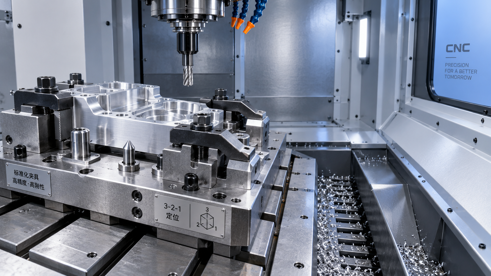
For rotational work, evaluate chucking method, collet condition, soft-jaw design, tailstock or steady-rest support, and the relationship between gripping surfaces and functional datums. For prismatic work, consider whether the fixture contacts stable areas, whether clamping force can distort the part, and whether the part can be accessed without repeated removal. Vacuum fixtures, custom soft jaws, hydraulic clamping, modular tombstones, and zero-point systems each have a place, but none is universally suitable.
It is also worth asking a practical question: can the part be measured in the same datum logic used to manufacture it? If inspection references differ from manufacturing references, disagreements about compliance become more likely. Clear datum translation is particularly important for parts with complex GD&T callouts.
A practical comparison for process selection
Volume changes the “right” answer
The best process for a one-off prototype is rarely identical to the best process for a stable production program. In low volumes, flexible CNC machining and adaptable fixturing may be economically sensible, even if cycle time is not minimal. The priority is often learning: validating tool access, confirming material behavior, and refining inspection methods before committing to dedicated equipment.
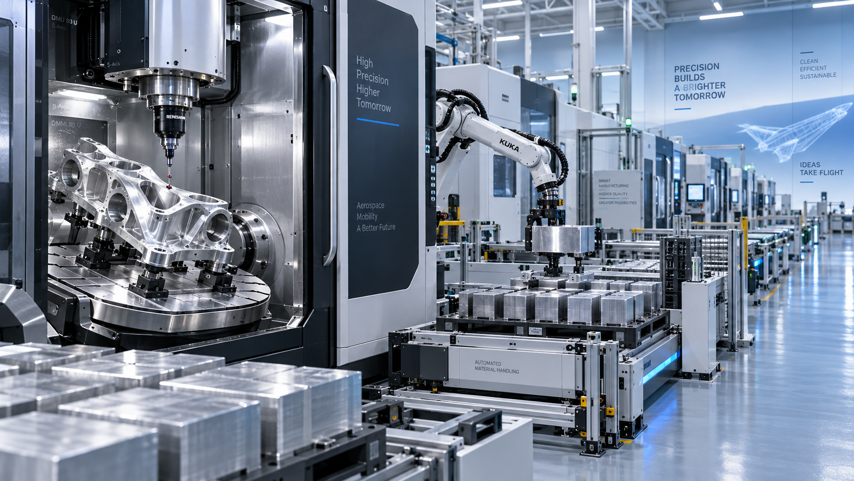
As volume rises, automation becomes more relevant. Bar feeders, pallet pools, robotic loading, in-process probing, tool monitoring, and automated gauging can reduce operator-dependent variation and support predictable output. But automation should be added around a proven process, not used to conceal an unstable one. Repeatedly loading a poorly fixtured part faster does not improve capability.
For recurring precision components, technical evaluators should compare total process cost rather than unit machining time alone. Include setup frequency, scrap exposure, inspection burden, tool consumption, secondary operations, material handling, and the cost of responding to out-of-tolerance conditions. A slightly longer cycle completed in one controlled setup may be preferable to a fast primary operation followed by several risky transfers.
Questions that reveal real machining capability
When assessing a machining supplier, production line, or internal manufacturing route, broad claims about “high precision” are less useful than specific process questions. Ask which features are finished in the same clamping, how thermal growth is managed, and what measurement method verifies the most demanding callouts. Request clarity on the planned machining sequence, not just the list of available machines.
Useful discussion points include whether in-process probing is used for work offset correction; whether critical bores are drilled, reamed, bored, honed, or ground; how tools are monitored for wear; and how a supplier controls parts after heat treatment. For complex five-axis work, ask how probing, simulation, and fixture verification are integrated before production starts.
Inspection capability should match the drawing’s risk profile. Calipers and micrometers remain appropriate for many features, but tight positional tolerances, freeform surfaces, and complex datum structures may require a CMM, optical measurement system, air gauging, roundness tester, surface roughness tester, or dedicated functional gauge. The important point is traceability between the required characteristic and the measurement method used to accept it.
Choosing an industrial machining route with fewer surprises
A sound decision balances capability with control. Choose turning when rotational relationships dominate. Use milling for versatile prismatic features and broad material removal. Add grinding where final hardness, finish, or geometric stability demands it. Consider EDM when material hardness or feature geometry defeats conventional cutting. Bring in multi-axis machining when reducing setups protects critical relationships or provides essential access.
Most tight-tolerance parts do not depend on a single process. They depend on a coordinated route in which material condition, fixturing, machining order, measurement, and automation support one another. For technical evaluators, that is the real test of industrial machining capability: not whether a facility owns advanced equipment, but whether it can explain—clearly and convincingly—how each operation preserves the dimensions that make the part work.
PREVIOUS ARTICLE
NEXT ARTICLE
Recommended for You
 Industrial Machining: Selecting Processes for Tight-Tolerance Metal PartsCNC Machining Technology Center
 Manufacturing Technology Trends That Improve Throughput and Quality ControlManufacturing Market Research Center
 How to Design Cost-Effective Fixtures That Maintain Cycle Time in Mass ProductionCNC Machining Technology Center
 Is Learning CNC Programming Worth It for Shop Owners Seeking Higher Margins?CNC Machining Technology Center
 CNC Machine Arrival Inspection: Check Shipping Damage, Accuracy, Safety, and DocumentsCNC Machining Technology Center
 How to Select a Machine Tool for Aerospace Parts with Tight Tolerances?Machine Tool Industry Editorial Team

Aris Katos
Future of Carbide Coatings
15+ years in precision manufacturing systems. Specialized in high-speed milling and aerospace grade alloy processing.
▶
Industrial Machining: Selecting Processes for Tight-Tolerance Metal PartsCNC Machining Technology Center▶
How Does Precision Machining Differ From Standard Machining?CNC Machining Technology Center▶
CNC Precision: Which Tolerances, Materials, and Processes Fit Your Part?CNC Machining Technology Center▶
How to Choose Metal Machining Processes for Tight Tolerances and Production VolumeCNC Machining Technology Center▶
Production Process Explained: Key Stages, Controls, and Quality CheckpointsCNC Machining Technology Center
Mastering 5-Axis Workholding Strategies
Join our technical panel on Nov 15th to learn about reducing vibrations in thin-wall components.

Providing you with integrated sanding solutions
Before-sales and after-sales services
Comprehensive technical support