• Global CNC market projected to reach $128B by 2028 • New EU trade regulations for precision tooling components • Aerospace deman
NYSE: CNC +1.2%LME: STEEL -0.4%

What Tolerances Are Typical in Precision Machining?
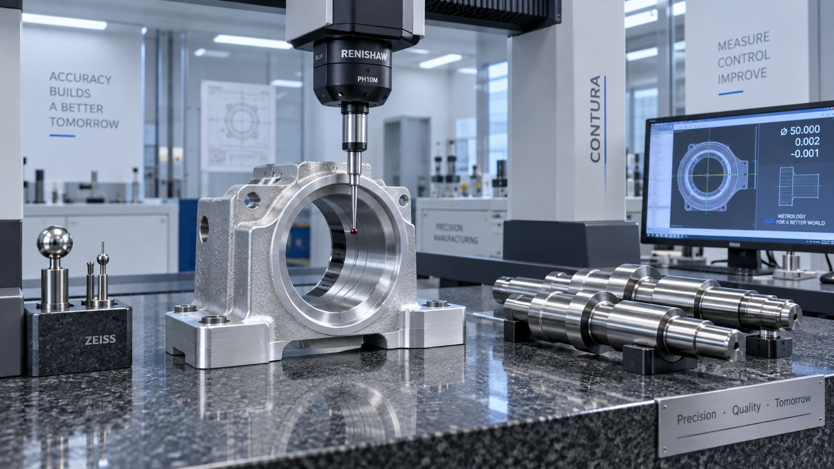
A bearing seat that is slightly oversized can prevent assembly; one that is undersized can allow unwanted movement. Yet applying the same tight tolerance to every surface on the part can increase machining and inspection costs without improving performance. For engineers asking what is the typical tolerance in precision machining, a practical starting point is ±0.005 to ±0.025 mm for selected precision CNC features. Less demanding dimensions often allow ±0.05 to ±0.10 mm, while requirements below ±0.005 mm usually need closer process review.
These ranges are planning guidance, not guaranteed capabilities. A short, rigid steel shaft and a thin-walled aluminum housing can behave very differently, even on the same machine. The useful question is whether a particular feature can consistently meet its limits after unclamping, finishing, and inspection—not simply whether the machine can move in small increments.
Which tolerance ranges should I use as a starting point?
The table below shows indicative dimensional tolerances for early design and supplier discussions. Actual capability depends on feature size, material, workholding, machine condition, production volume, and measurement method. The ranges overlap because process names alone do not establish accuracy.
A tolerance of ±0.01 mm is approximately ±0.00039 inch. When converting drawings, preserve the intended limits rather than rounding to a convenient decimal that changes acceptance criteria. Also avoid treating “precision machining” as a formal tolerance class: it describes a broad category of work, not a universal specification.
Does ±0.01 mm mean a 0.01 mm tolerance?
Not quite. For a dimension of 20.000 ±0.010 mm, the acceptable size runs from 19.990 to 20.010 mm. The total tolerance band is 0.020 mm. Distinguishing the allowed deviation from the total band prevents confusion when comparing drawings, quotations, and inspection reports.
Tolerances can also be unilateral. A bore specified as 20.000 +0.020/−0.000 mm may be anywhere from 20.000 to 20.020 mm. It has the same total band as the bilateral example but a different acceptable interval, which changes its relationship with a mating shaft.
Dimensional tolerance should not be confused with machine resolution, positioning accuracy, or repeatability. A controller displaying 0.001 mm increments does not prove that finished parts meet ±0.001 mm. Cutting forces, tool wear, thermal drift, fixturing, and measurement uncertainty remain part of the result.
Why can a shaft diameter be easier to hold than a thin housing?
A short external diameter turned in one setup often has favorable conditions: continuous cutting, straightforward measurement, and a relatively rigid workpiece. A deep pocket or thin wall may deflect under cutting pressure, distort under clamping, or move when residual stresses are released. Its final dimension can change after removal from the fixture.
Consider an aluminum electronics housing with a close-fitting lid. The external length may be easy to measure, but sealing performance could depend more on flange flatness and the relationship between mounting holes. Tightening every linear dimension does not necessarily control either problem. The drawing should target the surfaces and relationships that determine assembly.
Material matters as well. Hardened steel can require finishing after heat treatment because hardening may change size and shape. Plastics can respond strongly to temperature, moisture, and clamping pressure. Thin stainless steel features may combine deflection with difficult cutting behavior. A tolerance demonstrated on one material should not automatically be transferred to another.
Access also affects capability. Long tools reaching into deep cavities are more vulnerable to deflection and vibration. Features machined in separate setups introduce additional locating variation, particularly when their relationship depends on transferring datums between fixtures.
Will a tighter size tolerance solve a fit or alignment problem?
Only when size is the controlling issue. Two parts can meet their individual diameter limits and still assemble poorly because of roundness, taper, position, or surface texture. A bore within its size limits may not guide a shaft correctly if its axis is misaligned with another bearing seat.
For a bearing installation, establish the required fit using the bearing supplier’s guidance, load direction, operating temperature, and housing or shaft material. Then specify the relevant size limits and any necessary geometric controls. Do not select an arbitrary “precision” tolerance and assume it creates a suitable fit.
Different requirements answer different functional questions:
- Size tolerance: Is the diameter, width, or length within the permitted limits?
- Position: Is a hole or other feature located correctly relative to defined datums?
- Flatness: Does a surface stay within the permitted form variation?
- Runout: Does a rotating surface vary acceptably relative to a datum axis?
- Surface roughness: Is the surface texture suitable for contact, sealing, friction, or appearance?
Apply geometric tolerancing using a specified drawing standard and clear datums. A numerical limit without an unambiguous reference system can leave the manufacturer and inspector evaluating different requirements.
How do I choose tolerances for mating parts?
Start with the allowable assembly condition, then work backward to the individual dimensions. For a clearance fit, the smallest hole and largest shaft determine minimum clearance. The largest hole and smallest shaft determine maximum clearance.
As an illustrative calculation, a hole of 10.000 to 10.020 mm paired with a shaft of 9.980 to 9.990 mm produces diametral clearance from 0.010 to 0.040 mm. Whether that is acceptable depends on the application; the calculation does not establish suitability for a bearing, seal, or sliding mechanism.
Assemblies with several contributing dimensions need a tolerance stack-up. A bracket, spacer, housing shoulder, and shaft length may each meet their drawing requirements while their combined variation creates excessive end play or interference. Tightening only the easiest dimension may have little effect on the final condition.
Use worst-case stack-up when every permitted combination must assemble. Statistical methods can be useful for controlled production, but their assumptions about distribution, centering, and independence require evidence. They should not be used simply to justify looser tolerances.
When does asking for a tighter tolerance increase cost?
Cost rises when the existing process no longer has enough margin to maintain the requirement reliably. Moving from ±0.05 mm to ±0.01 mm may require a finish pass, improved tooling, or more frequent measurement. Moving further may demand grinding, thermal stabilization, specialized workholding, or a different process sequence.
The burden is not limited to cutting time. Tighter limits can increase setup effort, inspection time, tool replacement, and the risk of rejection. A single demanding feature can determine the route for the entire component, particularly when heat treatment or coating occurs between rough machining and final finishing.
Quantity changes the decision. A one-off part may receive extensive adjustment and individual inspection. A production run needs a stable process as tools wear and conditions change. One conforming sample demonstrates feasibility, but it does not demonstrate reliable production capability.
Before tightening a requirement, identify the failure it prevents. A locating bore may justify a close limit because it determines alignment. A noncontact exterior surface usually does not benefit from the same control unless it serves another measurable function.
Can inspection confirm tolerances of only a few micrometers?
Yes, but the inspection method must be appropriate to the feature and acceptance limits. Calipers are useful for many general checks, but they are usually unsuitable for accepting features with tolerance bands of only a few micrometers. Suitable micrometers, bore gauges, air gauges, or coordinate measuring equipment may be needed.
Instrument resolution is only one consideration. Calibration, measuring force, part cleanliness, alignment, temperature, and operator technique contribute to uncertainty. A device displaying fine increments can still produce measurements that are inadequate for the acceptance decision.
Temperature becomes increasingly important as limits tighten. Dimensional specifications are commonly referenced to 20°C unless otherwise defined. Parts measured while warm from machining may give different results after stabilization, especially when their material expands differently from the gauge or fixture.
Agree on the measurement approach before production:
- Which datums and fixture conditions will be used?
- Will parts be measured free-state or restrained, particularly for flexible components?
- Are dimensions required before or after coating, plating, or heat treatment?
- What sampling plan and acceptance rule apply?
A coordinate measuring machine is not automatically the best answer for every feature. Accessible diameters may be checked efficiently with dedicated gauges, while complex positional requirements may benefit from coordinate measurement. The method must support the specific requirement.
What should I send a machine shop to confirm capability?
Provide a drawing that identifies critical features, rather than relying on the CAD model alone. Include material condition, finish requirements, datums, geometric controls, and the manufacturing state at which dimensions apply. State the governing drawing standard and revision.
General tolerances can cover noncritical dimensions, with explicit limits assigned to functional features. Avoid a blanket ±0.005 mm note unless every applicable dimension genuinely needs it. Such a note can impose unnecessary restrictions on depths, edge distances, and exterior surfaces that do not control performance.
Ask the supplier to review the most demanding features individually. Useful questions address the proposed process, finishing allowance, inspection method, and whether capability refers to a prototype or sustained production. A statement that a machine is “accurate to five microns” is not a substitute for that review.
Should tolerances apply before or after finishing?
Specify the condition that matters in use. Plating and coating can alter mating dimensions, while heat treatment can cause distortion. When fit depends on the finished surface, the drawing should make the final acceptance condition explicit and address masking or post-treatment machining where necessary.
Deburring also deserves attention on small features. Removing a burr can affect an edge, opening, or narrow land, while leaving it in place can obstruct assembly despite acceptable measured dimensions. Define critical edge requirements separately instead of expecting a tight size tolerance to control them.
For a new part, reserve tight tolerances for the features that establish fit, motion, sealing, or alignment. Confirm those requirements against the proposed material, process sequence, and inspection method before release. That is more useful than selecting one “typical” tolerance for the whole drawing.
Recommended for You
![]() 33rd JIMTOF 2026 Set to Open in Tokyo as Taiwanese Exhibitors Seek OrdersGlobal Machine Tool Trade Research Center
 Which Fixture Type Cuts Changeover Time Most in High-Mix CNC Machining?CNC Machining Technology Center
![]() FANUC Invests $18 Million in Largest U.S. Corporate Automation Training CenterMachine Tool Industry Editorial Team
 Southeast Asia Machine Tool Market: Comparing Automotive Demand by CountryManufacturing Market Research Center
![]() Zhongshan Xiaolan Machinery Exhibition Opens With Global Product DebutsMachine Tool Industry Editorial Team
 Automated Production Machining: Which Parts and Batch Sizes Are a Good Fit?Machine Tool Industry Editorial Team


Aris Katos
Future of Carbide Coatings
15+ years in precision manufacturing systems. Specialized in high-speed milling and aerospace grade alloy processing.
▶
How thermal drift affects accuracy in high-precision manufacturingCNC Machining Technology Center▶
What Tolerances Are Typical in Precision Machining?CNC Machining Technology Center▶
Industrial Machining: Selecting Processes for Tight-Tolerance Metal PartsCNC Machining Technology Center▶
How Does Precision Machining Differ From Standard Machining?CNC Machining Technology Center▶
CNC Precision: Which Tolerances, Materials, and Processes Fit Your Part?CNC Machining Technology Center
▶
Mastering 5-Axis Workholding Strategies
Join our technical panel on Nov 15th to learn about reducing vibrations in thin-wall components.

Providing you with integrated sanding solutions
Before-sales and after-sales services
Comprehensive technical support