• Global CNC market projected to reach $128B by 2028 • New EU trade regulations for precision tooling components • Aerospace deman
NYSE: CNC +1.2%LME: STEEL -0.4%

How Does Precision Machining Differ From Standard Machining?
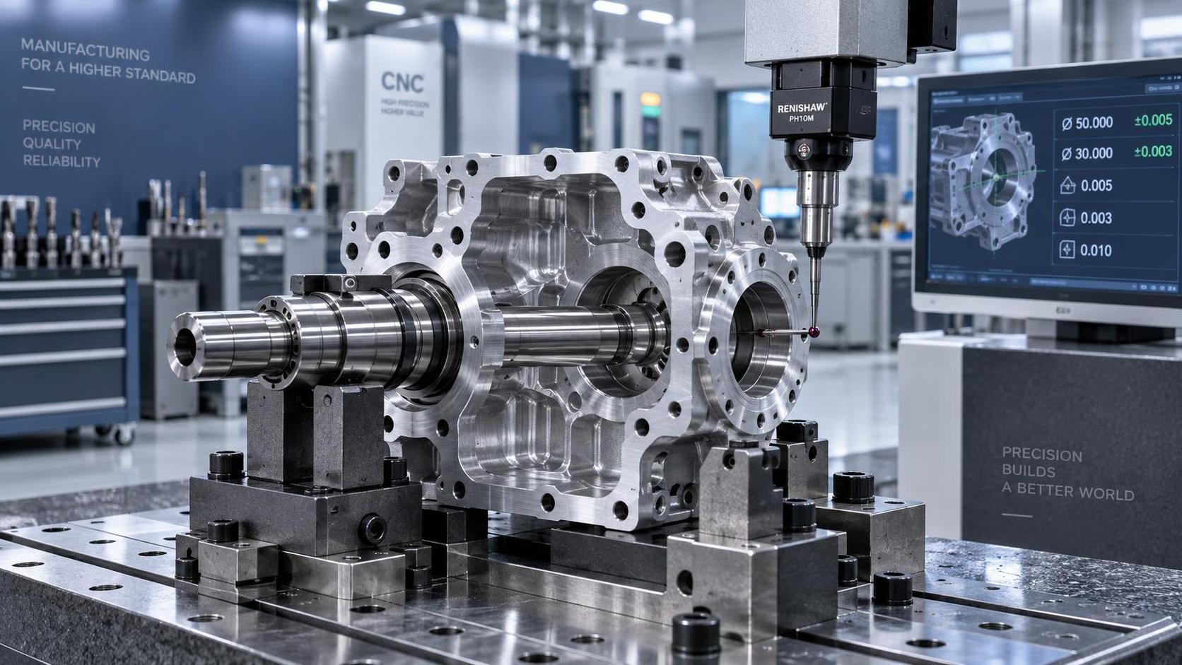
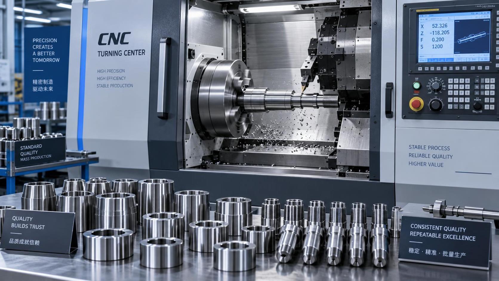
Precision machining differs from standard machining in more than the ability to hold a smaller dimension. It is a manufacturing approach built around tighter tolerances, more controlled processes, more capable equipment, and more rigorous inspection. Standard machining is often the practical choice when a part only needs to fit, function, and be produced efficiently. Precision machining is used when small variation can affect sealing, motion, electrical performance, safety, assembly, or service life.
The distinction matters because a drawing can look simple while the required manufacturing method is not. A round shaft, flat plate, threaded body, or machined housing may all be produced on CNC equipment, but the acceptable variation in size, geometry, surface finish, and material condition determines whether standard or precision machining is appropriate.
It Is Not Just About “Tighter Tolerance”
People often describe precision machining as “machining with very high accuracy,” which is true but incomplete. A part can meet one tight diameter tolerance and still fail because a bore is not concentric with its outside diameter, a sealing face is not flat enough, a thin wall distorts after machining, or the surface finish causes excessive wear.
Standard machining usually works within tolerances that are suitable for general fabrication and ordinary mechanical assembly. The shop selects tooling, workholding, cutting conditions, and inspection methods that deliver reliable output at a reasonable production cost. Small variations are expected, provided they remain within the functional requirements of the part.
Precision machining treats variation as a process risk that must be controlled from setup through final inspection. The machine must be capable of repeatable positioning. The fixture must locate the part consistently. Tools must be monitored for wear. Thermal changes, vibration, material stress, cutting forces, and measurement uncertainty all require attention. In other words, precision is not a finishing step added after machining; it is designed into the manufacturing process.
The Real Difference Appears in Process Control
On a standard job, an operator may machine a batch, inspect selected features, adjust offsets when needed, and confirm that the parts remain acceptable. This is appropriate for many components. It becomes less reliable when a part has narrow dimensional limits or multiple features that must align accurately with one another.
Precision work usually requires a more deliberate process plan. Datums are chosen carefully so that the part is referenced from the surfaces that matter in final assembly. Machining order is planned to reduce distortion. Roughing and finishing may be separated so that the final cut is made under stable conditions. A part may be allowed to cool before a critical finishing operation, especially when its shape or material makes it sensitive to heat.
Tool condition is another major difference. A worn tool does not always create an obvious defect. It may gradually change a bore size, leave a poorer finish, increase burr formation, or introduce taper. In standard machining, that change may still fall within the drawing requirement. In precision machining, the same drift can consume the available tolerance before the batch is complete. Tool life management, offset compensation, and controlled replacement intervals therefore become part of the quality strategy.
Workholding deserves equal attention. A fixture that clamps a part too aggressively can deform it during machining. When the clamp is released, the part may spring back and no longer measure correctly. Thin-walled housings, rings, discs, and long shafts are especially vulnerable. Precision machining often relies on custom jaws, soft clamping, support points, or staged setups to control this effect. The fixture is not merely a way to hold the material; it is part of the accuracy system.
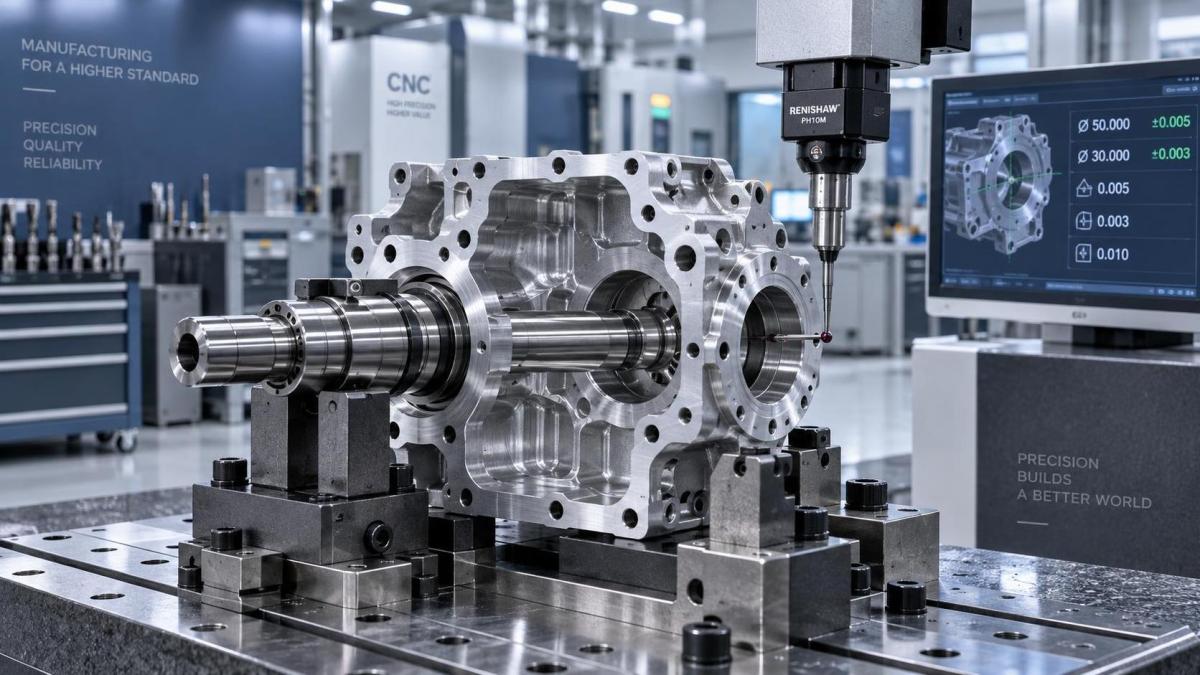
Accuracy Includes Geometry, Not Only Size
A dimension such as diameter or thickness is easy to understand because it can be checked directly. Yet many expensive machining failures involve geometric tolerance rather than a simple linear size. A shaft may have the right diameter but run out when rotating. A flange may have the correct bolt-hole dimensions but sit at an angle because the mounting face is not perpendicular. A valve body may contain bores of the right size that do not line up along the required centerline.
Precision machining is more likely to be needed when the drawing controls:
- Roundness, cylindricity, straightness, flatness, or parallelism.
- Concentricity or coaxial relationships between turned and milled features.
- Perpendicularity between bores, faces, and mounting surfaces.
- Position accuracy for hole patterns, slots, or threaded features.
- Surface finish on a sealing, sliding, bearing, or optical contact area.
- Fits between mating parts where clearance or interference must be predictable.
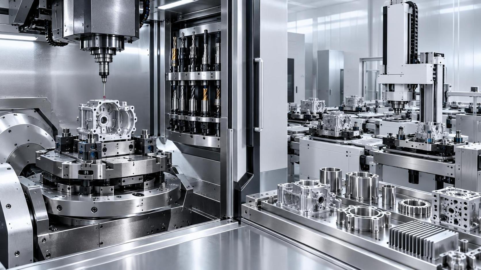
These requirements often affect the process more than the nominal part size. A multi-axis machining center can machine several faces in one setup, reducing errors created by repeatedly removing and relocating the workpiece. A CNC lathe can establish critical diameters and shoulders from the same datum. For complex rotational components, a mill-turn or multi-axis system may reduce handling while maintaining relationships between features. The right equipment depends on the part, but fewer uncontrolled setups generally make tight geometric requirements easier to manage.
Surface Finish Can Change Whether a Part Works
Standard machining may leave a surface that looks acceptable and is suitable for noncontact or cosmetic areas. Precision machining gives more attention to surface texture because the microscopic peaks and valleys left by a cutting tool can influence friction, sealing, fatigue behavior, coating adhesion, and wear.
A polished appearance is not automatically a precision finish. Some surfaces need a controlled texture rather than the smoothest possible result. A sealing face may need low roughness to reduce leak paths. A sliding component may need a finish that supports lubrication. A surface that will be coated may require preparation that helps the coating bond reliably. The drawing or functional requirement should determine the finish target, not an assumption that smoother is always better.
Material selection also changes the challenge. Aluminum, stainless steel, tool steel, titanium, engineering plastics, and cast materials react differently to heat and cutting forces. Some materials build up on cutting edges. Others work-harden, spring back, or release internal stress after material removal. Precision machining accounts for these behaviors through tool geometry, feeds and speeds, coolant strategy, stock allowance, and machining sequence.
Inspection Is a Production Activity, Not a Final Gate
In a standard machining workflow, final inspection may focus on confirming the main dimensions before shipment. That approach is sufficient when a rejected part can be replaced without disrupting the assembly or causing broader quality problems.
Precision parts are commonly inspected at several points because discovering a deviation after all machining is complete can waste expensive material and production time. The measurement method must also be appropriate for the tolerance. Calipers are useful for many general dimensions, but they are not the right tool for every bore, runout condition, profile, or surface requirement. Micrometers, bore gauges, height gauges, dial indicators, optical systems, and coordinate measuring equipment each answer different questions.
Measurement conditions matter as well. A part that has just left a machine may be warmer than the inspection area. A long, thin component can flex under its own weight. Burrs can create misleading readings at an edge. Even a good measuring instrument produces poor decisions when the datum, support method, or inspection sequence is inconsistent.
This is why a capable precision supplier should be able to explain not only how it will machine a critical feature, but also how it will verify it. For a demanding component, asking for “tight tolerance” without discussing the inspection method leaves a major part of the requirement undefined.
When Standard Machining Is the Better Choice
Precision machining is not automatically the right answer. It adds planning, setup time, tooling attention, inspection effort, and sometimes slower cycle times. Applying it to every feature on every part can increase cost without improving the product.
Standard machining is often appropriate for structural brackets, guards, covers, base plates, simple mounts, rough prototype parts, and components with generous clearance in the final assembly. It can also be appropriate when a critical feature is limited to one area of the part. In that case, the drawing should identify that feature clearly instead of placing unnecessarily tight requirements across all dimensions.
A common mistake is to specify a blanket tolerance because the designer wants a “high-quality” part. This can create expensive inspection and rejection rates while offering no functional benefit. Good design practice separates features that truly control performance from those that simply need to be manufacturable and assemble without interference.
When Precision Machining Is Worth the Added Control
Choose a precision approach when a small dimensional change can alter how the product performs. Typical examples include mating bores and shafts, bearing seats, hydraulic or pneumatic sealing features, high-speed rotating components, tightly aligned electronic enclosures, precision discs, and parts with complex datum relationships.
It is also justified when consistency across a production batch is important. A part may work individually after hand fitting, but hand fitting is rarely a sound basis for repeatable assembly. When parts must interchange without adjustment, stable machining and inspection become more valuable.
Industries such as aerospace, automotive manufacturing, energy equipment, and electronics often contain both standard and precision-machined components. The deciding factor is not the industry label. A simple automotive bracket may only need standard machining, while a relatively small sensor housing can need carefully controlled geometry. Likewise, an energy system may include large, general-tolerance frames alongside sealing and rotating parts that demand much tighter control.
How to Decide Before Sending a Machining Request
The most useful first step is to connect each critical drawing requirement to a function. Ask what happens if the feature is slightly oversized, undersized, out of position, rougher than intended, or misaligned. If the answer is leakage, vibration, premature wear, failed assembly, unstable measurement, or safety risk, that feature needs a defined precision strategy.
- Identify functional interfaces. Mark surfaces that locate, seal, rotate, slide, carry a bearing, connect electrically, or mate with another precision part.
- Define datums around assembly reality. Reference the surfaces the part will actually use in the finished product, rather than selecting datums only because they are easy to measure.
- Apply tighter requirements selectively. Tighten only the dimensions, geometry, and finishes that affect performance. Leave noncritical features practical.
- Consider the whole route. Include material behavior, heat treatment, coating, welding, and assembly. A part can move or distort after machining if later processes are not considered.
- Match inspection to the risk. State how critical features should be verified and whether batch sampling is sufficient or individual measurement is required.
For complex components, early discussion with a CNC machining provider can prevent a drawing from calling for an unnecessarily difficult process. CNC lathes, machining centers, and multi-axis systems each offer different strengths, and the best route may combine operations rather than force every feature onto one machine type. Tooling, fixtures, automation, and digital measurement are most effective when they are selected around the actual function of the part.
Do Not Confuse Precision With a Machine Label
A modern CNC machine can be highly capable, but CNC alone does not guarantee precision output. Machine condition, spindle behavior, axis calibration, programming, workholding, tooling, environmental stability, operator practice, and inspection discipline all influence the final result. A well-controlled conventional CNC process can produce excellent precision parts within its capability, while an advanced machine can still produce inconsistent results if the setup and quality system are weak.
The practical question is not “Do I need a precision machine?” It is: “Which features must remain consistent, what can cause them to vary, and how will the process prevent and detect that variation?” Answering that question leads to a machining plan that protects performance without paying for accuracy where it has no value.
NEXT ARTICLE
Recommended for You
 How Automated Precision Machining Maintains Tolerance in High-Mix ProductionCNC Machining Technology Center
 How to Evaluate a Machine Tool Factory Before Sourcing CNC EquipmentGlobal Machine Tool Trade Research Center
 CNC Programming Explained: From CAD Models to Reliable Shop-Floor ToolpathsCNC Machining Technology Center
 How Multi-Axis Machining Produces Complex Components With Fewer SetupsCNC Machining Technology Center
 How Does Precision Machining Differ From Standard Machining?CNC Machining Technology Center
 What Production Volume Justifies a CNC Turning Investment?Manufacturing Market Research Center



Aris Katos
Future of Carbide Coatings
15+ years in precision manufacturing systems. Specialized in high-speed milling and aerospace grade alloy processing.
▶
How Does Precision Machining Differ From Standard Machining?CNC Machining Technology Center▶
CNC Precision: Which Tolerances, Materials, and Processes Fit Your Part?CNC Machining Technology Center▶
How to Choose Metal Machining Processes for Tight Tolerances and Production VolumeCNC Machining Technology Center▶
Production Process Explained: Key Stages, Controls, and Quality CheckpointsCNC Machining Technology Center▶
How to Select a Machine Tool for Electronics Manufacturing with Tight Tolerance NeedsCNC Machining Technology Center
Mastering 5-Axis Workholding Strategies
Join our technical panel on Nov 15th to learn about reducing vibrations in thin-wall components.

Providing you with integrated sanding solutions
Before-sales and after-sales services
Comprehensive technical support