• Global CNC market projected to reach $128B by 2028 • New EU trade regulations for precision tooling components • Aerospace deman
NYSE: CNC +1.2%LME: STEEL -0.4%

Precision Machining for Optical Components: Tolerances, Materials, and Process Limits
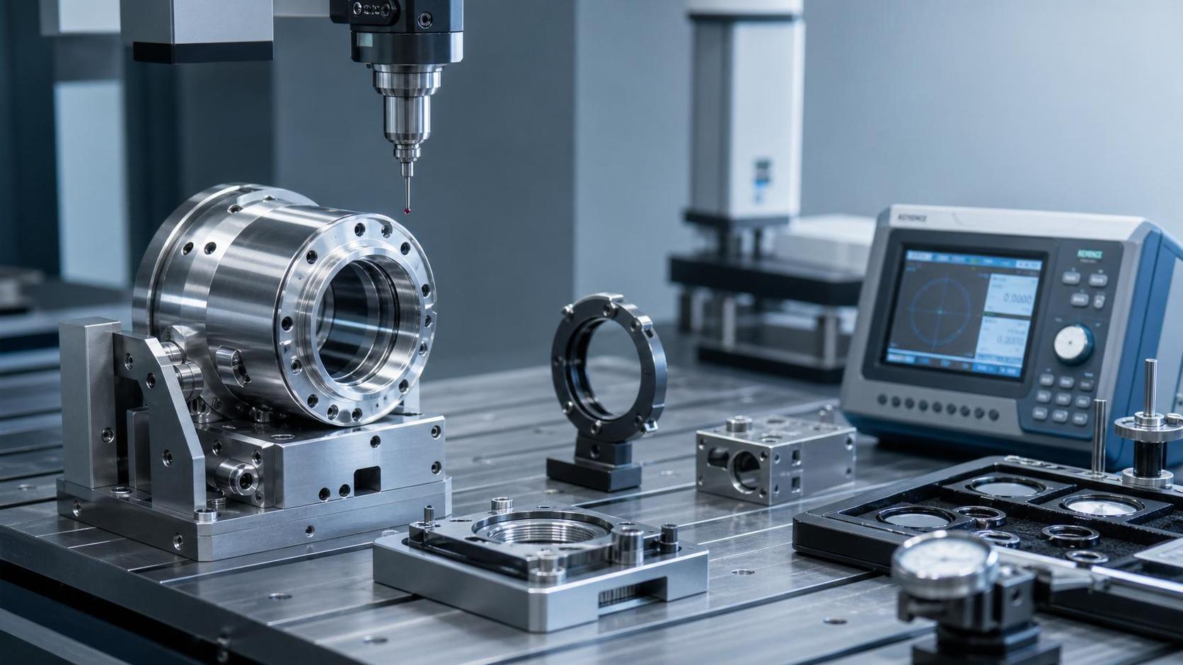
Precision Machining for Optical Components: Tolerances, Materials, and Process Limits
Precision Machining for Optical Components is central to stable optical performance and repeatable production quality.
In practice, small machining errors can become large inspection failures once alignment, coating, or assembly begins.
That is why tolerance control, material response, and process capability need to be reviewed together.
For optical housings, lens seats, mirrors, mounts, and precision brackets, dimensional accuracy alone is not enough.
Surface condition, thermal stability, burr control, and traceable inspection results directly affect downstream reliability.
This makes Precision Machining for Optical Components a process discipline, not only a machine capability question.
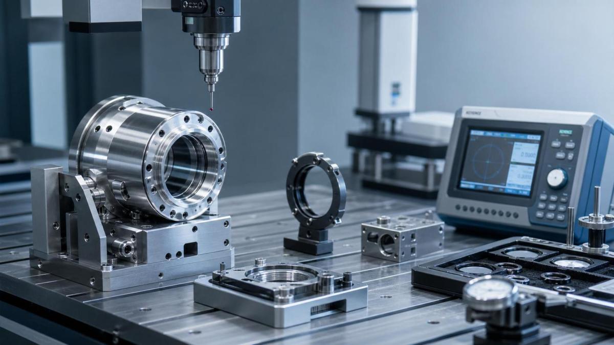
From a manufacturing perspective, the hardest issues usually appear at the edges of process limits.
Thin walls distort, brittle materials chip, and tight datums drift when heat and clamping are poorly managed.
A sound control plan starts with realistic tolerances and verified machining windows.
Why Tolerances Matter in Optical Part Manufacturing
Tolerance decisions in Precision Machining for Optical Components affect fit, alignment, sealing, vibration, and optical path stability.
Even when a part passes CMM checks, it may still fail functional assembly or final optical testing.
Common critical features include coaxiality, flatness, perpendicularity, datum position, and mounting interface geometry.
For lens barrels and mirror mounts, concentricity and thread quality often drive assembly yield.
For sensor frames and alignment plates, flatness and hole position are often the real control points.
In actual production, overly tight tolerances can increase scrap without improving optical function.
The better approach is to separate function-critical dimensions from cosmetic or non-critical features.
- Assign tighter limits to optical interfaces and datum chains.
- Use wider process windows for secondary faces and non-locating edges.
- Link every tight tolerance to a measurement method and acceptance rule.
This reduces unnecessary cost and makes Precision Machining for Optical Components more controllable at scale.
Typical Tolerance Ranges and Realistic Capability
A useful discussion about Precision Machining for Optical Components should start with achievable capability, not ideal drawings.
Process limits depend on machine condition, tooling, fixturing, environment, and inspection uncertainty.
For many metal optical parts, general CNC milling may hold plus or minus 0.01 mm reliably.
With stable tooling and better thermal control, plus or minus 0.005 mm is often practical.
Below that level, the process usually needs specialized finishing, tighter climate control, and more frequent verification.
These values are reference points, not guaranteed outcomes for every geometry and material.
The more complex the part, the more likely local distortion or feature interaction will reduce capability.
This is where capability studies become useful before production release.
Material Behavior and Machining Risk
Material choice shapes the true limits of Precision Machining for Optical Components.
Aluminum alloys are widely used because they machine quickly and support lightweight optical assemblies.
Still, some grades move after roughing, especially when parts have thin ribs or asymmetrical pockets.
Stainless steel offers strength and corrosion resistance, but cutting heat and tool wear increase rapidly.
Titanium adds another layer of difficulty because of heat retention and springback.
Engineering plastics can be dimensionally stable in service, yet sensitive during machining and inspection.
Moisture absorption, temperature change, and low clamping stiffness can shift readings significantly.
For brittle optical materials or ceramic-related parts, edge chipping and microcracks become the main concern.
In these cases, conventional CNC methods may need to be paired with grinding or lapping.
- Use stress-relieved stock for thin and highly symmetric optical structures.
- Review coefficient of thermal expansion against assembly and service temperature.
- Check whether anodizing, coating, or passivation will shift critical dimensions.
Material data sheets help, but shop-floor behavior is the stronger guide for risk planning.
Process Limits: Heat, Fixturing, Tool Wear, and Surface Quality
The main process limits in Precision Machining for Optical Components usually come from four sources.
They are thermal variation, fixture distortion, cutting tool degradation, and surface integrity loss.
Thermal growth is easy to underestimate.
A small temperature shift in machine structure, workpiece, or gauge can move a tight tolerance out of range.
Fixturing creates another hidden limit.
If a thin optical mount is over-clamped, it may pass in the fixture and fail after release.
Tool wear changes both size and finish.
On optical support parts, roughness drift can interfere with sealing faces, adhesive bonding, or precision seating.
Burrs also deserve more attention than they often receive.
A small burr near a lens seat or datum edge can mislead assembly and damage delicate components.
- Set machine warm-up and environmental monitoring as standard controls.
- Use soft jaws, vacuum fixtures, or low-distortion supports where geometry allows.
- Define tool life by measured drift, not by operator judgment alone.
- Add burr inspection points before coating and final cleaning.
These controls improve repeatability more than simply demanding tighter print limits.
Inspection Standards and Verification Strategy
Inspection for Precision Machining for Optical Components should match the actual failure modes of the part.
That means combining dimensional checks with surface, cleanliness, and feature-edge evaluation.
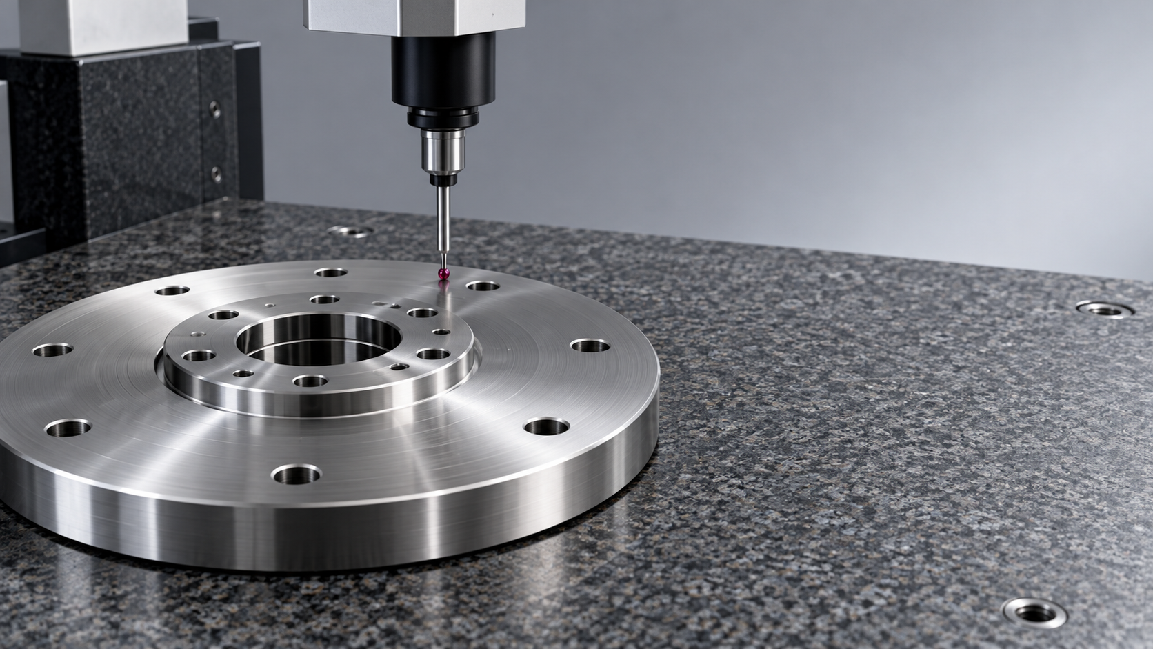
CMM systems are useful for datums, profiles, and position accuracy.
Optical comparators, roughness testers, thread gauges, and flatness tools remain important in daily control.
Gauge R&R should be reviewed when tolerances approach the noise level of the measurement system.
Without that step, data may look precise while decisions remain unreliable.
Many teams also miss the timing of measurement.
Checking a warm part too early can create false acceptance or false rejection.
- Define inspection temperature and part stabilization time.
- Connect critical characteristics to control plans and reaction plans.
- Use first article, in-process checks, and final audit for layered verification.
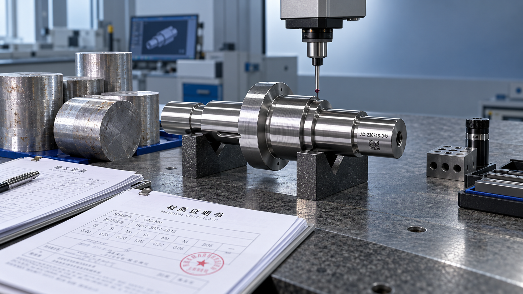
- Retain traceable records for tooling changes, offsets, and nonconformance decisions.
This is especially important when customer specifications reference ISO, GD&T, or internal validation standards.
Practical Actions to Improve Yield and Compliance
A practical Precision Machining for Optical Components program does not begin with expensive equipment alone.
It begins with realistic requirements, stable methods, and disciplined feedback from machining to inspection.
The strongest results usually come from a short list of repeatable habits.
- Review drawings for function-critical tolerances before release to production.
- Match material grade and heat treatment to part geometry and service environment.
- Confirm fixture stress, thermal drift, and tool wear through pilot runs.
- Set inspection methods according to measurement uncertainty and defect mode.
- Use nonconformance data to adjust process windows, not only to sort defects.
When these steps are in place, Precision Machining for Optical Components becomes easier to scale across suppliers and product lines.
It also supports cleaner audits, faster root cause analysis, and more predictable optical assembly outcomes.
The key point is simple.
Precision Machining for Optical Components succeeds when tolerances, materials, process limits, and inspection standards are managed as one system.
Recommended for You
![]() Mitsubishi Electric Announces Physical AI System Linking Humanoid Robots and CNC MachinesMachine Tool Industry Editorial Team
Mitsubishi Electric Announces Physical AI System Linking Humanoid Robots and CNC MachinesMachine Tool Industry Editorial Team Precision Machining for Defense: Supplier Quality and Traceability ChecksManufacturing Market Research Center
![]() Nidec Machine Tool Launches MVR-5X Five-Axis Gantry MachineMachine Tool Industry Editorial Team
Nidec Machine Tool Launches MVR-5X Five-Axis Gantry MachineMachine Tool Industry Editorial Team Choosing a Precision Disc Parts Manufacturer in China: Tolerances and Quality ChecksManufacturing Market Research Center
![]() Siemens Executive Says AI Could Raise Factory Automation to 80%Manufacturing Market Research Center
Siemens Executive Says AI Could Raise Factory Automation to 80%Manufacturing Market Research Center Choosing Automated Machine Tools for High-Mix, Low-Volume ProductionMachine Tool Industry Editorial Team


Aris Katos
Future of Carbide Coatings
15+ years in precision manufacturing systems. Specialized in high-speed milling and aerospace grade alloy processing.
▶
How thermal drift affects accuracy in high-precision manufacturingCNC Machining Technology Center▶
Industrial Machining: Selecting Processes for Tight-Tolerance Metal PartsCNC Machining Technology Center▶
How Does Precision Machining Differ From Standard Machining?CNC Machining Technology Center▶
CNC Precision: Which Tolerances, Materials, and Processes Fit Your Part?CNC Machining Technology Center▶
How to Choose Metal Machining Processes for Tight Tolerances and Production VolumeCNC Machining Technology Center
▶
Mastering 5-Axis Workholding Strategies
Join our technical panel on Nov 15th to learn about reducing vibrations in thin-wall components.

Providing you with integrated sanding solutions
Before-sales and after-sales services
Comprehensive technical support