• Global CNC market projected to reach $128B by 2028 • New EU trade regulations for precision tooling components • Aerospace deman
NYSE: CNC +1.2%LME: STEEL -0.4%

Can Industrial Robots Load and Unload CNC Machines Safely? Key Safeguards
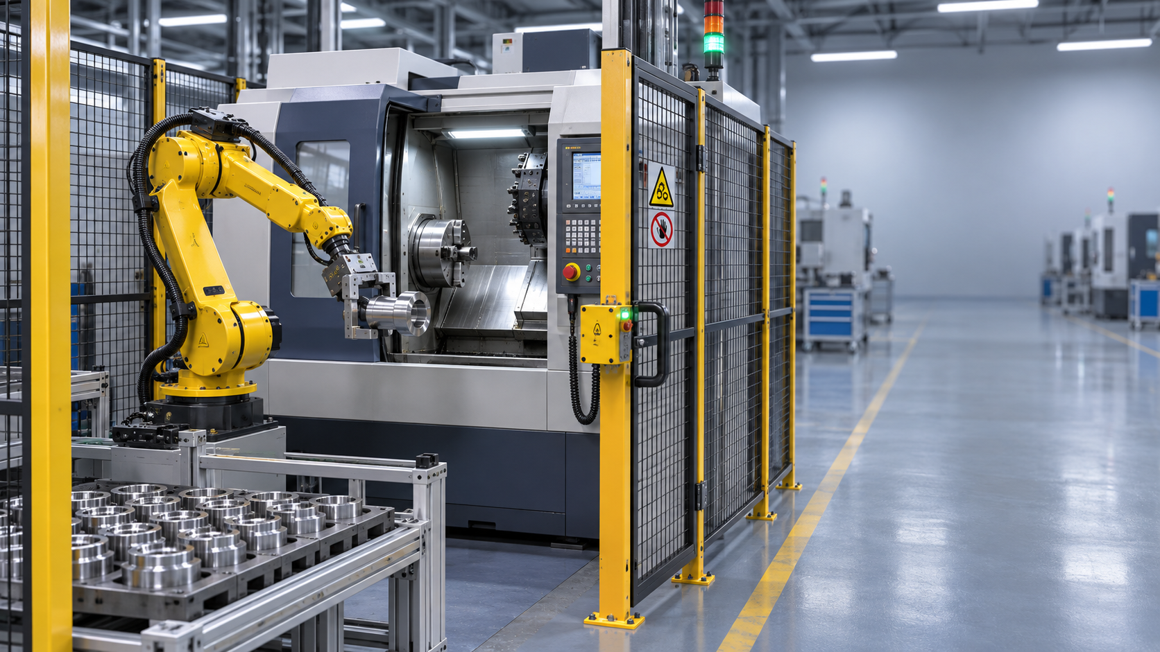
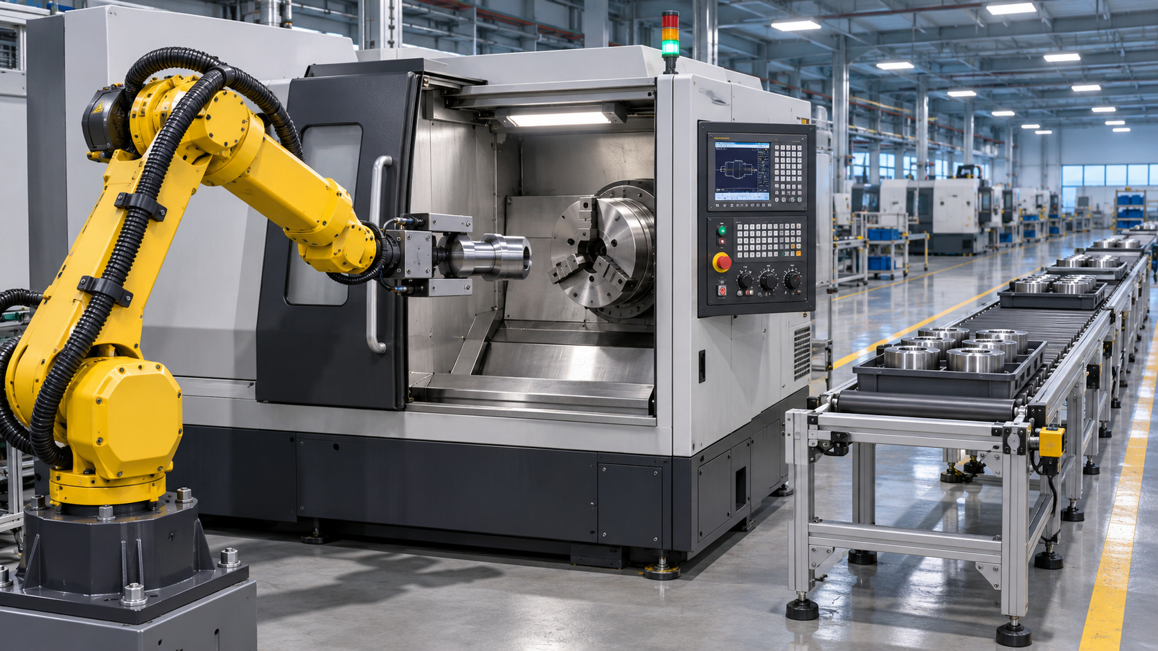
Yes. Industrial robots can load and unload CNC machines safely when the robot, machine tool, guarding, and control system are designed and validated as one cell. Safe operation depends on more than keeping people away from the robot: the design must also control spindle motion, chuck movement, machine doors, dropped parts, unexpected restarts, and access during fault recovery.
A cell that runs safely through a normal production cycle can still expose people to danger when a blank jams in a gripper or a finished part remains in the chuck. Those interruptions, together with setup and maintenance, often determine whether the safeguards are adequate.
Start with the complete handling cycle
A useful risk assessment follows the workpiece from the infeed to the finished-part location. It includes every robot pose, gripper action, machine-door movement, and transfer into or out of the chuck or fixture. The assessment also covers activities outside automatic production: changing jaws, clearing chips, replacing gripper fingers, measuring a first part, teaching a robot position, and recovering from a power interruption.
The boundaries of the cell matter. A robot may reach beyond its programmed path if a program changes or a fault occurs, so guarding should account for the space required by the robot, tooling, and carried part. A long shaft can sweep through an area that appears clear when only the robot arm is considered. The part’s momentum and possible release also affect the choice and placement of barriers.
Record the hazardous situations, the protective measures selected, and the assumptions behind them. For example, a gripper designed around dry, uniform blanks needs review if incoming stock later arrives oily or with larger dimensional variation. Reassessment is also needed when a new fixture, robot path, part family, or access method changes the original conditions.
Keep access separate from hazardous motion
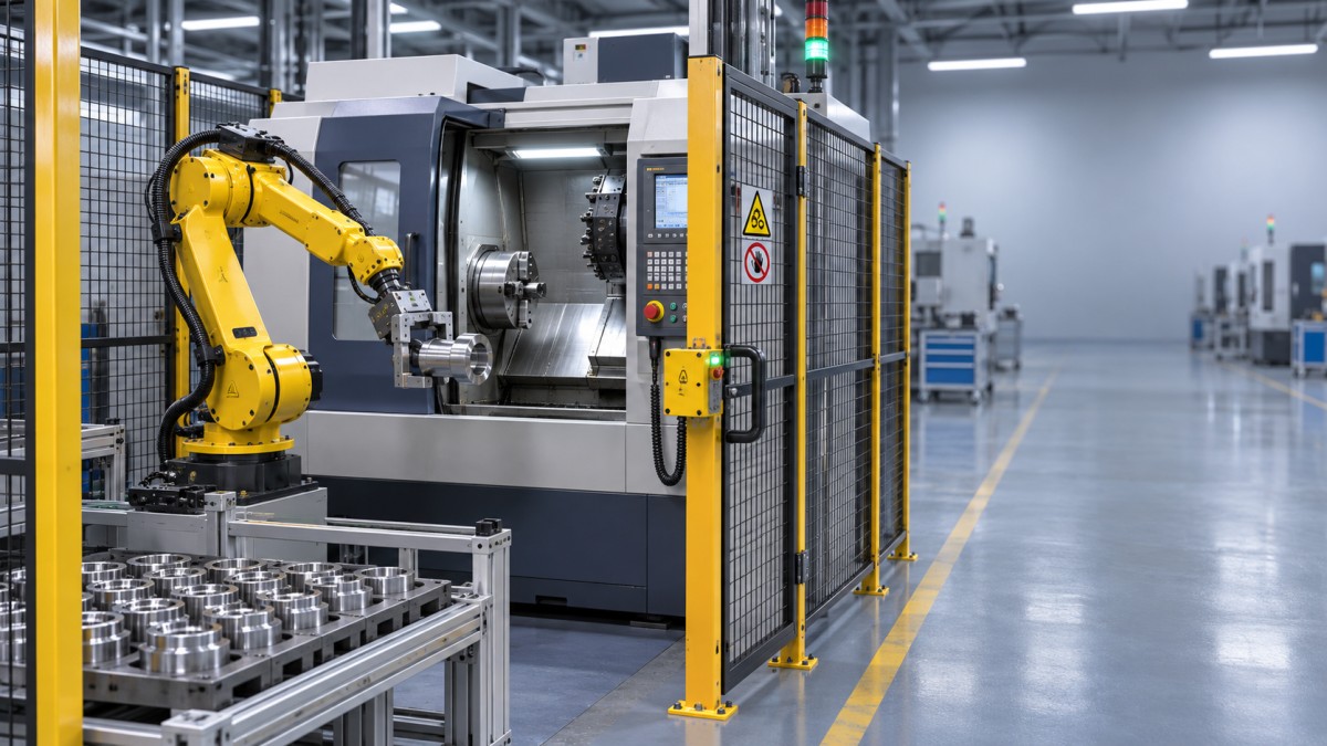
Fixed perimeter guarding and interlocked access doors are common safeguards for CNC machine-tending cells. The barrier must prevent reaching through, over, or under it into hazardous areas, including the pinch points around the CNC door and the robot’s part-transfer position. Its location must also account for how far a person can reach and how long the relevant motion takes to stop.
An interlocked door should cause the required protective stop when opened or unlocked. Where motion or another hazard continues after the stop request, guard locking can keep the door closed until access is safe. A signal that the robot has stopped does not automatically establish that the spindle, chuck, automatic door, or other equipment is safe to approach; the release condition must cover the hazards present at that access point.
Light curtains or area scanners can support access where a physical door would obstruct material flow. Their effectiveness depends on placement, detection capability, stopping performance, and whether someone can reach the hazard by going around, over, or under the sensing field. Coolant mist, chips, and reflections can also affect reliable detection and require attention during installation and validation.
A normal cycle stop and an emergency stop serve different purposes. Emergency stops provide a readily accessible way to initiate an emergency stopping function; they do not replace guards or isolation for servicing. The required stopping behavior must consider the possibility of a suspended part falling if gripper power is removed.
Make the robot and CNC machine agree on each transfer
The robot should enter the machine only after the machine has reached a verified transfer state. That state typically includes a stopped spindle, a door confirmed open, and the appropriate chuck or fixture condition. The CNC machine should start its cycle only after the robot and its tooling have cleared the hazardous area, the workpiece is confirmed clamped, and the machine door is confirmed closed and locked where required.
These conditions require more than a sequence of ordinary production commands. The safety-related control functions need an architecture suited to the assessed risk, including appropriate devices, wiring or communication, fault response, and validation. A standard input saying “door open” may be useful for sequencing, but it does not by itself establish a safety-rated permission for access or motion.
Pay particular attention to signals that sound equivalent but represent different facts:
- Commanded open and confirmed open: a door command does not prove that the door reached its position or that its path is clear.
- Clamp command and clamp confirmation: a pressure signal or actuator position alone may not prove that the correct part is seated securely in the jaws.
- Robot at a programmed point and robot clear: clearance must account for the gripper and the workpiece, not just the arm.
- Cycle complete and safe to enter: a completed program does not necessarily confirm that all relevant motion has stopped.
Each transfer should have an agreed sequence for normal operation and an explicit response when a confirmation is missing or contradictory. If the machine reports a clamped part while the gripper still detects that same part, the cell should stop in a defined state rather than continue with an assumed transfer. Timeouts and diagnostic messages can make the fault easier to identify, but the safety function must not rely solely on an alarm being noticed.
Design the grip around real part conditions
Workpiece retention affects both personal safety and machining quality. A blank dropped during travel can become a projectile or create an obstruction; a blank placed off-center can damage jaws, tooling, or the machine. Select the gripping method with the part’s mass, shape, surface condition, center of gravity, and acceleration during travel in mind. Include the effect of coolant, cutting oil, chips, and variation in the incoming blank.
Grip force alone is an incomplete measure. Excessive force can distort thin-walled parts, while inadequate contact or worn fingers can allow a part to slip even when the actuator reports normal pressure. For a heavy or irregular component, mechanically enclosing features or a retention device may be appropriate. A vacuum gripper requires particular attention to surface condition, seal integrity, and what happens if vacuum is lost.
Define the gripper’s behavior during loss of electrical power, air pressure, or vacuum. A grip that opens on power loss can drop the load; a grip that remains closed can complicate safe recovery. The chosen behavior should be compatible with the cell layout and the recovery procedure. Where a falling part remains a credible hazard, keep people out of the drop zone until the load is supported or otherwise secured.
Part-present sensing helps detect missed picks and failed releases, but sensor placement matters. A sensor that detects a part in the gripper does not prove correct orientation or full seating in the machine fixture. For a turned shaft, for example, a reversed blank may still trigger a presence sensor. If orientation affects safe clamping or the machining cycle, it needs a separate verification method suited to the part.
Control access during setup and recovery
Automatic mode is only one operating state. Teaching, inspection, cleaning, and jam removal can place a person close to equipment that normally runs behind a closed guard. Define how each mode is selected, what motion is permitted, which safeguards remain active, and how the cell returns to automatic operation. Mode selection should be controlled so that a production command cannot silently restore automatic motion while someone is inside.
For teaching or setup that requires motion with a guard open, the arrangement needs risk-appropriate protective measures, such as controlled reduced motion and an enabling device where applicable. Reduced speed alone does not eliminate crushing hazards: a slowly moving robot can still trap a hand against a fixture. The entire space around the robot and machine door must remain visible enough to assess the movement being initiated.
After a protective stop, identify the cause before resetting. Resetting a safety function should not itself restart the robot or CNC cycle; a separate, deliberate start action is needed after the cell has been returned to a safe condition. Reset controls should be positioned so that the relevant hazardous area can be observed. Where the whole area cannot be seen, the design needs an additional way to account for anyone inside before restart.
Maintenance and interventions that expose people to hazardous energy require an appropriate isolation procedure. Electrical isolation alone may leave stored pneumatic, hydraulic, mechanical, or gravitational energy. A raised robot arm, spring-loaded fixture, pressurized chuck circuit, or suspended workpiece can remain hazardous after the main supply is switched off. Isolation points and methods should be established for the equipment and task, with stored energy relieved or restrained before work begins.
Validate the cell in conditions that challenge it
Validation should demonstrate that the installed safeguards and control functions perform as intended, including the interfaces between the robot and CNC machine. Review the design, inspect the installation, and test the relevant functions against documented acceptance criteria. Stopping performance should be measured under representative conditions that include the robot configuration, payload, speed, and tooling that affect the result. Use those results to verify protective-device placement and guard-locking release conditions.
Test more than a successful cycle. Open each interlocked access point during relevant motion, interrupt a transfer, remove a part from the expected pickup position, and simulate missing or inconsistent confirmations where this can be done safely. Observe whether the cell stops as intended, preserves or safely releases the load, reports the fault, and prevents an unexpected restart. Tests must be planned so that creating a fault does not itself expose anyone to danger.
Quality validation belongs alongside safety validation because handling faults can be subtle. Compare part seating, orientation, clamping marks, and dimensional results across the expected range of blanks and operating conditions. A shift in a machined feature can originate from chip contamination on a locating face, gripper positioning, jaw wear, or fixture clamping; blaming the CNC program alone can leave the handling fault in place.
Keep the validated configuration identifiable: robot program and safety settings, tooling, fixture, part range, protective-device positions, and machine interface. When one of these changes, assess which safety functions and quality checks need to be repeated. That record gives a practical basis for deciding whether an apparently small change has altered the conditions under which the cell was accepted.
Recommended for You
![]() Perpetua Resources Signs MOU to Evaluate US Tungsten Supply ChainManufacturing Market Research Center
 Choosing an Automated Lathe: Bar Capacity, Accuracy and Production VolumeCNC Machining Technology Center
![]() US Cutting Tool Shipments Reach $287.6 Million in September 2026Machine Tool Industry Editorial Team
 Choosing a Machine Tool Supplier: Service, Lead Times and Total CostManufacturing Market Research Center
![]() India Announces Domestic Five-Axis CNC Machine With 2-Micron AccuracyMachine Tool Industry Editorial Team
 Integrating Industrial Automation into Existing Production Lines: Key StepsMachine Tool Industry Editorial Team


Aris Katos
Future of Carbide Coatings
15+ years in precision manufacturing systems. Specialized in high-speed milling and aerospace grade alloy processing.
▶
Integrating Industrial Automation into Existing Production Lines: Key StepsMachine Tool Industry Editorial Team▶
Can Industrial Robots Load and Unload CNC Machines Safely? Key SafeguardsMachine Tool Industry Editorial Team▶
Automated Production Line Quotation: What Costs Should Buyers Check?Machine Tool Industry Editorial Team▶
How to Integrate Warehouse Palletizing Robots with Minimal DowntimeMachine Tool Industry Editorial Team▶
FANUC Invests $18 Million in Largest U.S. Corporate Automation Training CenterMachine Tool Industry Editorial Team
▶
Mastering 5-Axis Workholding Strategies
Join our technical panel on Nov 15th to learn about reducing vibrations in thin-wall components.

Providing you with integrated sanding solutions
Before-sales and after-sales services
Comprehensive technical support