• Global CNC market projected to reach $128B by 2028 • New EU trade regulations for precision tooling components • Aerospace deman
NYSE: CNC +1.2%LME: STEEL -0.4%

How to evaluate a Yunnan CY Group CNC lathe for your production
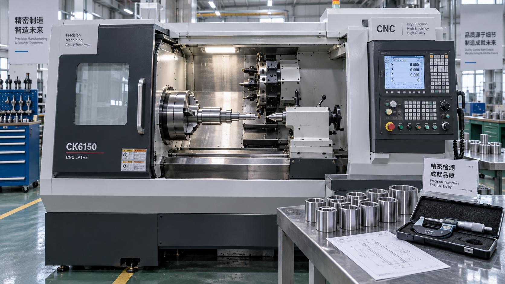
A Yunnan CY Group CNC lathe is a suitable production choice when the specific model and configuration can hold your part tolerances, meet the required output, and remain supportable in your factory. Maximum turning diameter, spindle speed, and motor power help narrow the shortlist, but they do not establish whether the machine will perform reliably on your work.
Build the evaluation around representative parts and measurable acceptance criteria. A machine that handles a short steel component efficiently may struggle with a slender shaft, an interrupted cut, or a thin-walled sleeve. The purchasing decision should connect documented specifications to cutting results, operating requirements, and the cost of producing accepted parts.
Start with a production requirement the supplier can demonstrate
Choose a small set of parts that represents the work the lathe will actually perform. Include the component that drives your volume and another that exposes the hardest machining condition. The largest part is not necessarily the most demanding: a smaller component with tight concentricity or a deep bore may create greater process risk.
Give the supplier drawings, material specifications, incoming stock conditions, and the features that determine acceptance. Identify which dimensions must remain related across setups. For example, turning a bearing seat and its reference diameter in one clamping can simplify control of their relationship; transferring the part introduces another source of variation.
A useful evaluation brief should include:
- Part dimensions, stock form, material condition, and expected variation in blanks.
- Critical tolerances, surface finish, geometric requirements, and inspection methods.
- Required output, batch sizes, changeover frequency, and shift pattern.
- Planned workholding, tooling, loading method, and secondary operations.
- Available floor space, utilities, operator skills, and maintenance resources.
Separate essential requirements from desirable features. A machine that cannot meet a critical bore tolerance should leave the shortlist regardless of its purchase price. Conversely, additional axes may offer little value if all planned work consists of straightforward turning and drilling.
Check the usable machining envelope
Catalogue capacity describes boundaries, but your complete setup must fit inside them. Swing over the bed is different from usable turning diameter with the selected turret, tools, and chuck. Nominal machining length also needs to accommodate jaws, tool approach, tailstock support, and safe clearance.
For bar-fed production, examine the complete material path. Spindle bore alone does not establish usable bar capacity: the drawtube, collet or chuck arrangement, spindle liner, and feeder interface can impose additional limits. Long or irregular stock also changes the support and loading requirements.
Ask for a layout using your proposed chuck, jaws, tools, and representative workpiece. Check turret indexing clearance, access for boring bars, tailstock interference, and part removal. These details can reveal whether a nominally adequate lathe requires compromises that increase setup time or restrict cutting conditions.
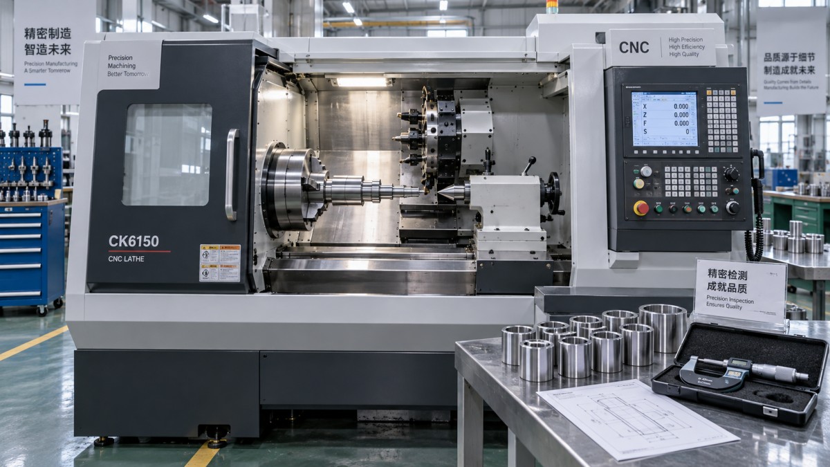
Workholding deserves particular attention for thin walls and short gripping lengths. Excessive clamping force can distort a component, while insufficient grip can allow movement during machining. Evaluate the chuck and jaw arrangement as part of the process, including the condition of the part after it is released.
Match spindle performance and rigidity to the cut
Maximum spindle speed is useful for small diameters, but larger workpieces often require substantial torque at lower speeds. Request the spindle power and torque curves, including continuous and short-duration ratings. A peak motor figure does not show what the machine can sustain throughout a production cycle.
The relationship between material, diameter, and cutting conditions determines the relevant operating range. Large steel blanks, interrupted surfaces, or heavy roughing cuts place different demands on the spindle and structure from small aluminium parts. Compare candidate machines at the speed and load your process requires.
Rigidity involves the entire cutting system: machine structure, spindle, turret, toolholder, workholding, and workpiece support. Chatter during a deep boring operation may be driven by tool overhang rather than insufficient motor power. A slender shaft may need a tailstock or steady rest even when spindle capacity is ample.
Use the trial to examine these interactions. If acceptable finish requires very shallow cuts or substantially reduced feed, the resulting cycle time may undermine the purchase case. A suitable setup should produce stable cuts with realistic tool overhang and enough capacity to accommodate normal stock variation.
For supported shafts, include tailstock alignment, quill arrangement, and support pressure in the assessment. Support can control deflection, but excessive force can distort the part or influence its dimensions.
Distinguish machine accuracy from finished-part capability
Positioning accuracy and repeatability describe axis behaviour under defined test conditions. Finished-part accuracy also depends on temperature, cutting forces, tool wear, clamping, material stress, and measurement practice. A positioning specification cannot, by itself, guarantee a diameter or geometric tolerance.
Ask how accuracy figures were measured and under what conditions. Travel length, machine temperature, compensation settings, and the measurement method affect how useful a specification is for comparing machines.
For the cutting trial, inspect more than one convenient external diameter. Include the features that expose likely weaknesses: taper along a shaft, roundness after unclamping, bore size at different depths, or the relationship between features machined in separate operations.
Thermal behaviour matters when tolerances are tight or shifts are long. Evaluate parts after the agreed warm-up and across a representative operating period. Frequent manual offset changes can indicate that a process needs more intervention than the production plan allows.
The measurement system must also suit the tolerance being assessed. Define instruments, measurement locations, part temperature conditions, and inspection timing before the trial. Otherwise, differences in measurement practice can obscure the machine’s actual performance.
Evaluate tooling, controls, and automation as a complete configuration
For a Yunnan CY Group lathe quotation, identify the exact control, turret, chuck, spindle arrangement, and included options. Model names alone are insufficient for comparing offers because configuration differences can change both capability and cost.
Check whether the turret accepts the holders and tools you intend to use. Station count is only part of the question. Large boring bars, adjacent-tool interference, coolant connections, and indexing clearance can reduce the number of stations practically available.
If the parts require cross-drilling, flats, or off-centre features, evaluate the proposed live tooling and axis arrangement against those operations. Combining operations can reduce transfers and handling, but adds programming and setup demands. Separate turning and milling may remain practical when secondary work is limited or existing equipment has spare capacity.
Control compatibility affects daily operation. Examine program transfer, tooling offsets, alarm diagnosis, backup procedures, and compatibility with your CAM postprocessor. Include an operator in the demonstration: routine recovery after a tool change or interrupted cycle should be understandable and repeatable.
Automation requires a stable machining process before it can deliver dependable output. For bar feeding or robot loading, examine the loading interface, chuck confirmation, part detection, chip removal, and recovery sequence. If connected production is planned, specify the machine states and data required, then demonstrate access through the quoted interface.
Chip control is especially important during unattended operation. Long chips can wrap around tools or obstruct part unloading. Assess chip-breaking behaviour, coolant delivery, conveyor suitability, and bin access using the actual material and cutting conditions.
Make the cutting trial a purchasing test
A demonstration should answer whether the proposed machine can run your process sustainably. Agree on the trial conditions before cutting starts, and record any differences between the demonstration machine and the quoted configuration.
Use enough consecutive parts to observe meaningful variation. One acceptable component shows feasibility, but provides little evidence about drift, tool wear, or repeated loading. The appropriate trial length depends on the tolerance, material, cycle, and production risk.
Distinguish automatic cycle time from total production time. Loading, inspection, chip clearing, tool replacement, and scheduled maintenance all influence output. If an operator must remove tangled chips after each cycle, that intervention belongs in the capacity calculation.
Where process capability analysis is appropriate, use a stable process, a suitable measurement system, and an adequate sample. A capability figure drawn from a short, carefully adjusted demonstration can create unjustified confidence.
Check installation and support before comparing total cost
A machine that performs well in a showroom still needs a workable installation plan. Review foundation and levelling requirements, electrical supply, compressed air, coolant management, ambient conditions, and access for delivery. Space must accommodate service access, conveyors, feeders, and safe loading.
Support arrangements should be concrete. Establish who handles commissioning, operator training, fault diagnosis, warranty work, and spare parts. For overseas purchases, include the service location, communication arrangements, and responsibility for travel or freight in the commercial discussion.
Maintenance documentation and access matter because routine tasks affect availability. Examine lubrication points, filters, consumable components, control backups, and procedures for restoring machine settings. Identify parts whose replacement could cause extended downtime and agree on a practical supply arrangement.
Compare the installed production cost, including tooling, workholding, transport, installation, training, automation interfaces, and any required extraction or coolant equipment. Then consider operating costs such as tool consumption, scrap, setup labour, and downtime. A lower purchase price can lose its advantage when the process demands constant correction.
Set approval conditions that reflect production risk
Use mandatory acceptance gates before a weighted comparison. Part quality, usable capacity, safe workholding, and required process capability should pass independently. Price, convenience features, and optional expansion can then differentiate machines that meet those essentials.
Carry the demonstrated process into the purchase agreement: configuration, representative part, tooling assumptions, acceptance measurements, output conditions, documentation, and training. Define what will be checked before shipment and what will be repeated after installation.
Approve the Yunnan CY Group CNC lathe when the evidence supports the production requirement and the installation and support arrangements are workable. If the trial exposes a limitation, identify whether tooling, workholding, an option, or a different machine size can resolve it, then repeat the affected test. The decision should rest on a reproducible process that produces accepted parts at the required pace.
PREVIOUS ARTICLE
NEXT ARTICLE
Recommended for You
![]() FANUC Invests $18 Million in Largest U.S. Corporate Automation Training CenterMachine Tool Industry Editorial Team
 Southeast Asia Machine Tool Market: Comparing Automotive Demand by CountryManufacturing Market Research Center
![]() Zhongshan Xiaolan Machinery Exhibition Opens With Global Product DebutsMachine Tool Industry Editorial Team
 Automated Production Machining: Which Parts and Batch Sizes Are a Good Fit?Machine Tool Industry Editorial Team
![]() FANUC Links FIELD System Data with Copilot to Advance Shop-Floor Data UseCNC Machining Technology Center
 Smart Manufacturing for Aerospace: Building Traceability Across CNC OperationsCNC Machining Technology Center



Aris Katos
Future of Carbide Coatings
15+ years in precision manufacturing systems. Specialized in high-speed milling and aerospace grade alloy processing.
▶
How to evaluate a Yunnan CY Group CNC lathe for your productionMachine Tool Industry Editorial Team▶
How to verify spare part compatibility for Yunnan CY Group lathesMachine Tool Industry Editorial Team▶
Is CNC Machining Hub Better Than Local Shops for Prototyping?Machine Tool Industry Editorial Team▶
German Hydraulic Parts Plant Sale Signals Local Supply ShiftMachine Tool Industry Editorial Team▶
How to Evaluate a Machine Tool Factory: 7 Checks Before Requesting a QuoteMachine Tool Industry Editorial Team
▶
Mastering 5-Axis Workholding Strategies
Join our technical panel on Nov 15th to learn about reducing vibrations in thin-wall components.

Providing you with integrated sanding solutions
Before-sales and after-sales services
Comprehensive technical support