• Global CNC market projected to reach $128B by 2028 • New EU trade regulations for precision tooling components • Aerospace deman
NYSE: CNC +1.2%LME: STEEL -0.4%

CNC Fixture Design: Locating and Clamping for Accurate Machining
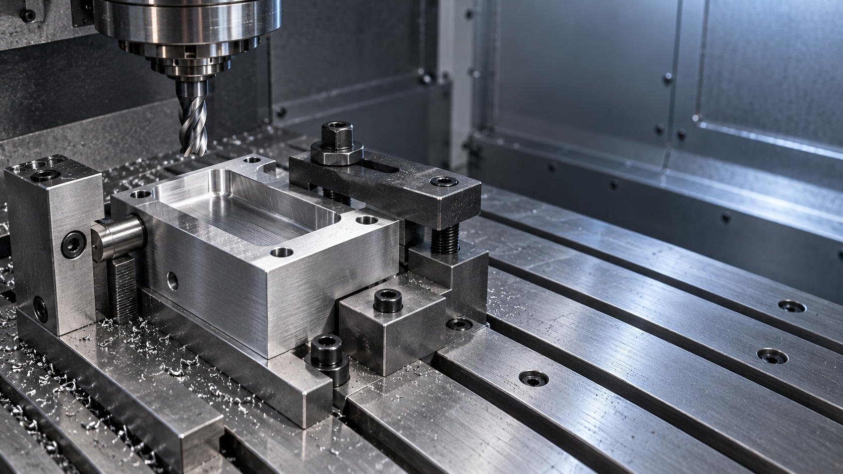
A CNC fixture can hold a workpiece firmly and still produce inaccurate parts. If the locating contacts do not establish a repeatable position, or if clamping bends the component before machining, the machine may reproduce the wrong geometry with excellent consistency. A sound fixture design starts by relating the part’s functional datums and tolerances to a stable locating scheme, then applies enough restraint to resist cutting forces without distorting the workpiece.
For a technical evaluator, the central question is not simply whether a fixture can secure the part. It is whether the complete setup can locate, support, clamp and release the part consistently under the intended machining conditions. The answer depends on part geometry, stock variation, tool access, cutting loads and the way accuracy will be measured after unloading.
Start With the Datum Structure
Before choosing clamps or locating pins, identify which surfaces and features control the finished part. A drawing may define a primary datum plane, a secondary datum and a tertiary datum, with positional or orientation tolerances referenced to them. The fixture should establish the machining coordinate system in a way that supports those relationships.
That does not always mean contacting the final datum features directly. On a first operation, those features may still be unmachined. The designer must then decide which raw surfaces can position the stock well enough to create reliable datums for later operations. Casting variation, saw-cut ends, scale and surface condition can all affect that choice. A fixture that repeats perfectly against an inconsistent raw surface may still produce variation in the finished part.
Consider a plate with holes controlled relative to a finished face and two perpendicular edges. Once those features are available, locating from them can make the relationship between the fixture and the drawing easier to control. In the first setup, however, locating from rough stock may require sufficient machining allowance and a check that the finished edges will remain within the available material.
Also distinguish between the fixture’s locating references and the machine’s work offset. Accurate setting of an offset cannot compensate for a part that seats differently on each load. Conversely, a repeatable fixture can still produce a systematic error if its position in the machine is established incorrectly.
Control Movement Without Forcing the Part Into Place
The familiar 3-2-1 locating principle is a useful starting point for a rigid prismatic part. Three contacts establish a primary plane, two contacts establish a secondary direction, and one contact establishes the remaining direction. Together, they constrain the six rigid-body degrees of freedom: translation along three axes and rotation about those axes. Clamps then maintain contact with the locators as cutting forces act on the part.
The arrangement only works as intended when the contacts are placed on suitable surfaces and the workpiece can seat against them. Spreading primary supports apart can improve stability, provided the contact areas are sound and the part is sufficiently rigid. The secondary and tertiary locators should be positioned to resist the expected lateral loads without obstructing loading or tool access.
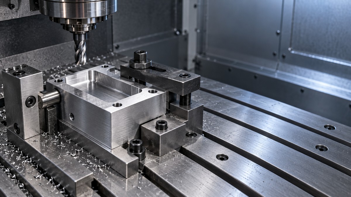
More contact points do not automatically improve accuracy. An extra fixed contact on an imperfect surface can prevent the part from seating on its intended primary locators. The result may be rocking, a different contact pattern from part to part, or deformation when the clamp is tightened. Where additional support is needed, an adjustable or compliant support can be brought into contact after the primary location is established. Its locking and loading sequence still matters: a support that lifts the workpiece changes the setup it was meant to stabilize.
Locating holes introduce a similar trade-off. A close-fitting round pin can establish position in two directions, but using another close-fitting round pin in a second hole can bind if hole spacing varies. A relieved or diamond pin at the second hole is a common way to control orientation while accommodating some spacing variation. The allowable clearance must still be assessed against the positional tolerance; added clearance can make loading easier while allowing more variation.
Not every part suits a 3-2-1 arrangement. Cylindrical components may be located on a bore, diameter or end face; thin sections may need distributed support; and irregular castings may require contacts selected around available stable areas. The underlying test remains the same: identify which contacts establish position, which provide support, and whether any of them compete with one another.
Clamping Force: Enough to Hold, Low Enough to Preserve Shape
Clamping must resist the forces and moments generated by the operation, including changes in tool engagement and cutting direction. It must also keep the workpiece against the intended locators. A clamp placed over or near a support generally has a shorter load path through the part than one pressing on an unsupported span. The latter can bend a thin wall or plate, even when the contact pressure appears modest.
The direction of force matters as much as its magnitude. A clamp that pushes toward a primary support can improve seating; one with a lateral component may shift the part, particularly if chips or clearance prevent full contact with the side locators. Clamp pads should contact suitable surfaces without damaging them or interfering with the cutter. For irregular or delicate surfaces, the pad shape and compliance deserve the same attention as the clamping mechanism.
Friction can help resist sliding, but it is sensitive to coolant, lubricant, surface finish and contamination. A design that relies entirely on friction should be evaluated for the least favorable credible contact condition. Positive stops or locators can provide a more predictable load path, though they too must be strong enough and positioned so cutting forces do not unload the primary supports.
Excessive force can create a particularly misleading result: the part measures correctly while clamped, then springs back after release. This is a concern for thin-walled housings, rings and long, slender components. Reducing the unsupported span, distributing support, changing the machining sequence or reducing cutting load may be more effective than simply increasing clamp pressure. In-process measurements are useful, but acceptance should reflect the specified free-state or restrained inspection condition.
For hydraulic or pneumatic clamping, assess pressure control and monitoring along with the clamp geometry. A pressure indication alone does not prove that the workpiece is fully seated or that every clamp has reached the intended contact. Where a pressure loss or incomplete clamp stroke could create an unacceptable hazard, the machine and fixture should be evaluated together for suitable interlocks and operator protection.
Design Around the Complete Machining Cycle
A fixture is part of the toolpath environment. Clamp bodies, fasteners, support posts and the fixture base must clear the tool, holder and spindle throughout cutting, approach and retract movements. On multi-axis machines, clearance must be checked across the full range of commanded orientations, not just in the initial setup view. A compact fixture can improve access, but reducing its mass or section size may compromise stiffness.
Chip evacuation is equally important to repeatability. A small chip trapped beneath a primary locator can tilt a part; a chip against a side stop can shift it. Contact points should be accessible for cleaning, and the loading sequence should make it practical to inspect them. Recesses that protect locators from direct chip impact can help, but they should not become pockets that are difficult to clear.
Loading also affects cycle time and error risk. The operator or automation system needs a clear way to orient the part, seat it against the locators and apply clamps in a consistent order. A fixture that requires one hand to hold the part against a stop while another operates a clamp may be workable for a prototype but less attractive for repeated production. Features that prevent an incorrect orientation are useful when they do not add unwanted locating constraints.
For a family of parts, adjustable or modular fixtures can reduce changeover effort. Their evaluation should include the repeatability of each adjustment, the number of settings an operator must make and the risk of using a setting intended for a different variant. A dedicated fixture may be justified where tight tolerances, high volume or limited tool access make those compromises costly.
How to Evaluate Accuracy Before Release
A fixture drawing or simulation can show the intended restraint, but it cannot by itself demonstrate repeatable seating. Evaluation should connect the design assumptions to the actual process: the range of incoming workpieces, the machining sequence, the clamping method and the inspection requirements.
- Check the constraint scheme. Identify the contacts responsible for each datum and degree of freedom. Confirm that supplementary supports do not lift or reposition the part when engaged.
- Check the load path. Review cutting-force directions and moments for the planned operations. Look for unsupported spans, possible lift-off and reliance on friction at contaminated or lubricated contacts.
- Check practical access. Verify tool and holder clearance, loading clearance, chip removal and access to clamp controls in every required machine orientation.
- Check part condition after release. Compare measurements in the specified inspection condition with any measurements taken while clamped, especially where deformation or springback is plausible.
- Check repeatability through reloading. Repeatedly unload, clean and reload a representative part, then measure relevant locations or machined features. Include realistic variation in stock and operating conditions when assessing production capability.
Interpret results carefully. Repeat loading of one part can reveal seating variation, but it does not establish how the fixture behaves across a range of incoming stock. Variation in a machined feature can also come from the machine, tool, thermal conditions or measurement method. Separating those contributors is necessary before attributing the whole error to the fixture.
The most useful acceptance discussion therefore follows the tolerance chain from incoming surface to locator, from locator to machine coordinate system, and from machining to final inspection. When that chain is understood, fixture changes can be judged by their effect on the finished part, rather than by how rigid or elaborate the setup appears.
NEXT ARTICLE
Recommended for You
![]() Survey: 81% Expect US Cutting Tool Shipments to Rise or Hold Steady in 2026Machine Tool Industry Editorial Team
 CNC Fixture Design: Locating and Clamping for Accurate MachiningCNC Machining Technology Center
![]() US Decides Against New Tariffs on Robots, Industrial Machinery and PartsManufacturing Policy Research Center
![]() White House Section 232 Ruling: No New Machine Tool or Robot Tariffs, Calls for TalksManufacturing Policy Research Center
 How to Integrate Warehouse Palletizing Robots with Minimal DowntimeMachine Tool Industry Editorial Team
![]() AI Investment Lifts US September Equipment Demand; Core Capital Goods Orders Rise 0.5%Manufacturing Market Research Center



Aris Katos
Future of Carbide Coatings
15+ years in precision manufacturing systems. Specialized in high-speed milling and aerospace grade alloy processing.
▶
CNC Fixture Design: Locating and Clamping for Accurate MachiningCNC Machining Technology Center▶
Which Fixture Type Cuts Changeover Time Most in High-Mix CNC Machining?CNC Machining Technology Center▶
How to Design Cost-Effective Fixtures That Maintain Cycle Time in Mass ProductionCNC Machining Technology Center▶
Zero-Point Clamping or Modular Fixtures? Choosing a Faster CNC Changeover SystemCNC Machining Technology Center▶
How to Cut CNC Fixture Changeover Time Without Sacrificing Part AccuracyCNC Machining Technology Center
▶
Mastering 5-Axis Workholding Strategies
Join our technical panel on Nov 15th to learn about reducing vibrations in thin-wall components.

Providing you with integrated sanding solutions
Before-sales and after-sales services
Comprehensive technical support