• Global CNC market projected to reach $128B by 2028 • New EU trade regulations for precision tooling components • Aerospace deman
NYSE: CNC +1.2%LME: STEEL -0.4%

How to Cut CNC Machining Energy Use per Part Without Longer Cycle Times
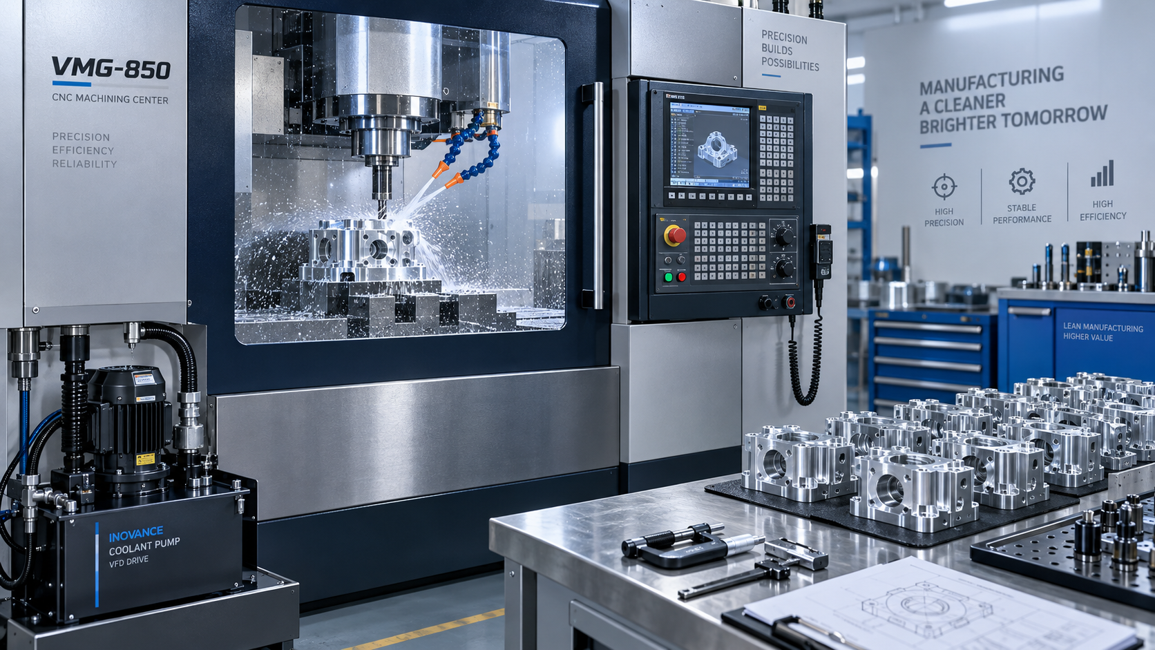
How to Cut CNC Machining Energy Use per Part Without Longer Cycle Times
Reducing CNC energy consumption should not mean slowing production or compromising part quality. The useful measure is energy per accepted part—not simply machine power. A lower spindle load can look attractive on a dashboard while a longer machining cycle keeps pumps, chillers, and controls running for additional time. The electricity bill may barely change, and production capacity may fall.
Effective energy-saving CNC manufacturing combines better toolpaths and cutting conditions with demand-based control of auxiliary equipment. The task is to identify unnecessary energy within the existing production cycle, then verify that removing it does not introduce tool wear, dimensional drift, or downstream delays.
That approach applies across CNC turning, machining centers, and multi-axis systems producing automotive shafts, aerospace structures, energy equipment, and precision electronic components. The details differ, but the acceptance rule stays consistent: less energy for conforming output, with no loss of throughput.
Set the measurement boundary before changing the process
Start with a definition that production, maintenance, and quality teams can all use:
Energy per accepted part = total energy within the agreed production boundary ÷ number of accepted parts produced.
The boundary matters. Measuring only the machine’s incoming electrical supply may exclude a central coolant system, extraction equipment, compressed air, or a separately powered chiller. Turning off a local pump and replacing its function with compressed air is not necessarily an energy saving; it may simply move consumption outside the meter.
Use two complementary views. Cycle-level energy helps evaluate machining changes. Batch- or shift-level energy captures warm-up, waiting, tool changes, scrap, and restart losses. A process can improve on the first measure and deteriorate on the second if it requires more frequent intervention.
For shared utilities, document how consumption is allocated. If compressed-air flow is measured rather than electrical input, state the assumptions used to translate that flow into attributable energy. Keep estimated utility consumption separate from directly metered values so uncertainty remains visible.
Also define “without longer cycle times.” Machine program time, load-to-load time, and production-line takt are different constraints. Saving machining seconds has little value if a robot must wait longer for coolant pressure recovery before the next operation.
Build an energy trace that explains where power goes
A single average-power reading cannot reveal the best improvement opportunities. Record actual electrical power over representative cycles and align it with machine events: spindle acceleration, cutting, rapid motion, tool changes, coolant operation, unloading, and waiting. Electrical measurement should be performed with suitable equipment by qualified personnel.
Choose a sampling interval short enough to distinguish the events being investigated. A slow plant-level meter may support shift reporting but miss brief pump starts or spindle acceleration. Controller spindle-load values can help interpret cutting behavior, but they are not a substitute for whole-machine energy measurement.
The most revealing comparison is often between ready-state demand and demand during cutting. If auxiliaries keep the machine drawing substantial power throughout the cycle, lowering cutting power alone may deliver a limited benefit. Conversely, frequent acceleration and deceleration may deserve attention on a short-cycle part with many separate operations.
An annotated trace should connect each power feature to an operation or equipment state. This makes it easier to distinguish necessary process demand from equipment running without a production requirement.
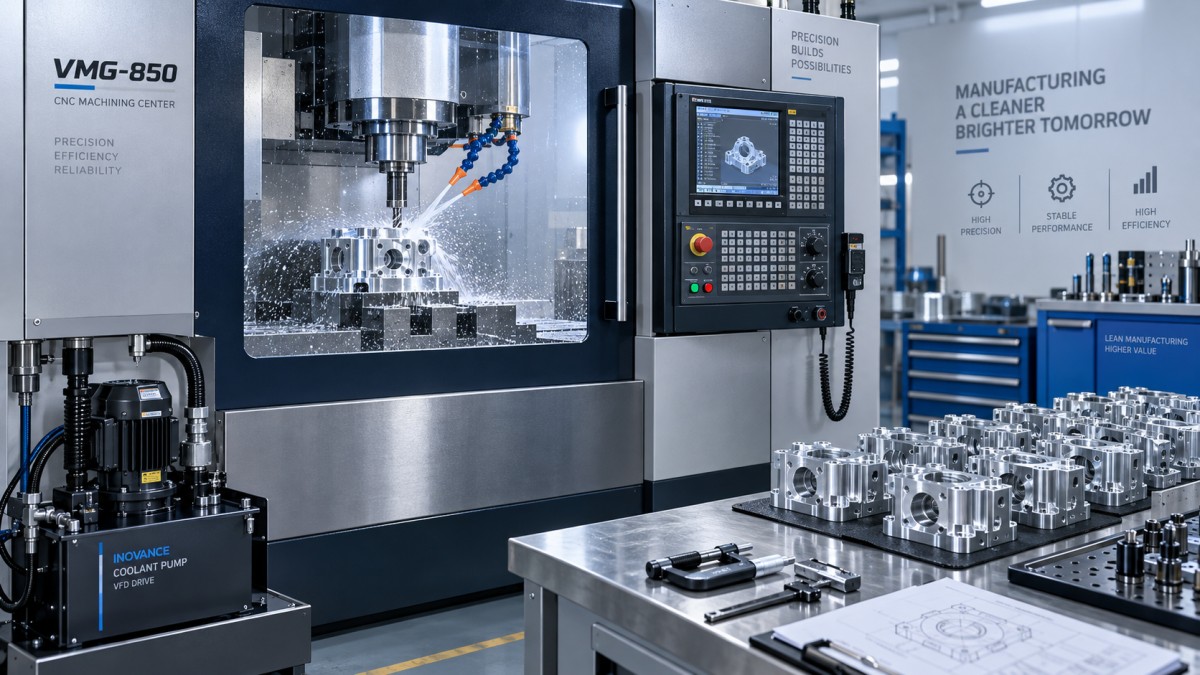
Record material condition, tooling, offsets, coolant settings, machine temperature, and program revision alongside the trace. Comparisons between a cold machine with a fresh tool and a thermally stable machine with a worn tool can produce misleading conclusions.
Optimize cutting without confusing lower load with lower energy
Reducing feed rate is an easy way to reduce instantaneous cutting power. It is not a dependable way to reduce energy per part. The longer engagement keeps the machine’s background systems active, and an excessively low chip thickness may encourage rubbing rather than efficient cutting.
Evaluate feed, speed, axial depth, and radial engagement together, within the tool supplier’s guidance and the machine’s operating limits. A higher material-removal rate may increase power while reducing total energy because the operation finishes sooner. However, it can also raise tool wear, deflection, vibration, or thermal loading. The energy meter cannot determine whether that trade-off is acceptable.
Remove motion that does not contribute to the part
Toolpath improvements are especially useful when they eliminate unnecessary travel rather than merely make cutting more aggressive. Review excessive retract heights, redundant passes, long linking moves, and repeated spindle-speed changes. Where access and process order permit, grouping operations by tool may reduce tool changes and spindle restarts.
Do not assume that the shortest geometric path is the fastest executable path. Tight corners, abrupt direction changes, and dense short segments can force the controller to decelerate. Smoother engagement and suitable toolpath transitions may improve actual feed performance, but they must preserve machining tolerance and collision clearance.
Constant-engagement strategies can stabilize cutting load, yet they may add travel. Compare measured cycle energy and actual execution time, not CAM estimates alone. For multi-axis work, unnecessary rotary-axis motion can also affect both energy demand and surface quality.
Any time recovered creates useful headroom. It may allow a less demanding cutting condition elsewhere while keeping total cycle time unchanged. Assess the complete program rather than requiring every operation to show an isolated power reduction.
Match auxiliary operation to real demand
Coolant pumps, chip conveyors, extraction systems, hydraulic units, and chillers deserve their own review. They can operate independently of material removal, which makes their control schedules important. The opportunity is not simply to switch equipment off more often; it is to provide the required service only when needed.
For coolant delivery, confirm the pressure and flow required at the tool. Blind holes, through-tool cooling, and difficult-to-machine materials may depend on reliable chip evacuation. Reducing pressure without checking these conditions can cause chip recutting, tool damage, or unstable drilling.
Where supported, staged pressure or demand-based pump control can avoid using the highest setting throughout the program. Include pressure-build time in the sequence: a pump that starts too late can create a dwell or expose the tool to inadequate coolant. Variable-speed operation also needs compatibility checks for the pump, motor, filtration system, and controller.
Other auxiliary changes require different safeguards:
- Chip conveyors: Intermittent operation must prevent chip accumulation around fixtures, drainage paths, and cutting zones.
- Hydraulics: Energy-saving states must retain required clamping pressure and comply with the machine builder’s approved control logic.
- Extraction: Operation must continue wherever exposure control requires it, including any necessary post-process run-on period.
- Chillers: Wider temperature bands or longer off-periods must not create spindle or structural temperature changes that affect precision.
Never bypass safety interlocks to implement an energy schedule. On older equipment, an approved control retrofit may be necessary before demand-based operation is practical.
Treat idle control as a scheduling decision
Idle-state management can reduce energy without extending machining time, but only if recovery fits the production schedule. Short loading gaps and long unattended stops should not trigger the same response. Frequent stop-start behavior may introduce restart delays or disturb thermal stability.
Establish a break-even idle duration: the point at which energy avoided during reduced-power operation exceeds additional transition and recovery energy. Then apply a separate production constraint—whether the machine can return to readiness before it is needed. For precision work, “ready” includes dimensional stability, not merely an illuminated control screen.
Robotic cells and flexible production lines can use scheduling signals to distinguish a brief material-transfer delay from a longer interruption. Check that automated wake-up functions are supported and validated. Digital connectivity is useful here because it coordinates states, not because a dashboard itself saves electricity.
Verify savings under production conditions
Start with a controlled trial on a stable part and process. Change one factor at a time where practical, or document interacting changes as a defined package. Preserve the baseline program and control settings so the comparison can be repeated and the original process restored.
Repeat baseline and modified runs under comparable conditions. An alternating test sequence can help reveal drift caused by temperature or tool wear. The required number of cycles depends on process variability and measurement uncertainty; a small difference should not be treated as proven if it sits within normal variation.
Approve a change only when the evidence addresses all of these questions:
- Has energy per accepted part fallen within the same measurement boundary?
- Are machine cycle time, load-to-load time, and line throughput maintained?
- Are dimensions, surface finish, and applicable integrity requirements still met?
- Have tool life, scrap, rework, and operator intervention remained acceptable?
- Does the saving persist across representative production and restart conditions?
A short trial is useful for screening, but it cannot establish tool life or long-term thermal behavior. Promising settings should move into a monitored production run before becoming the standard process.
Choose changes that remain controllable after handover
For existing CNC equipment, the most practical starting point is often an energy trace followed by toolpath cleanup and approved auxiliary scheduling. Hardware upgrades become easier to justify when measurements identify the subsystem responsible for avoidable demand.
When comparing new machines or retrofits from international suppliers, request energy evidence tied to a defined workpiece, program, utility boundary, and acceptance criteria. Installed motor ratings do not show energy per part, and consumption claims from unlike machining tasks are not directly comparable.
Document successful settings, restart conditions, rollback instructions, and checks required after tooling or material changes. The next step is not a factory-wide “eco” setting. It is one measurable process change that lowers energy, preserves output, and can be maintained reliably by the production team.
NEXT ARTICLE
Recommended for You
 How to Cut CNC Machining Energy Use per Part Without Longer Cycle TimesCNC Machining Technology Center
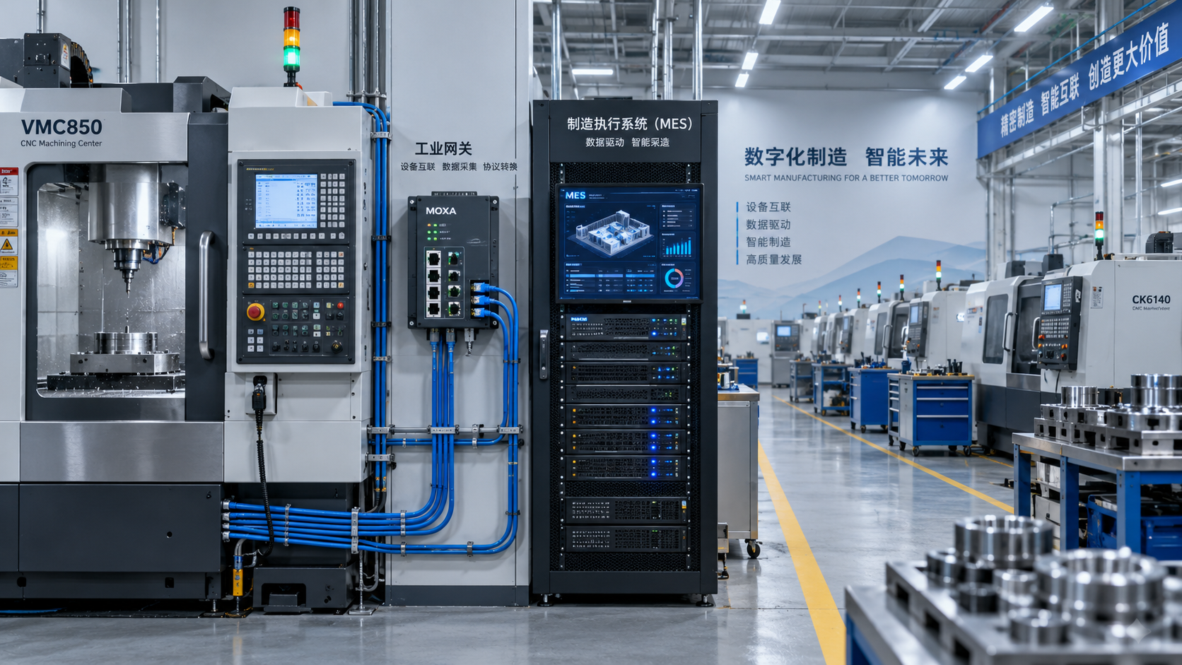
 Digital Manufacturing for Smart Factories: Connecting Legacy Machines to MESMachine Tool Industry Editorial Team
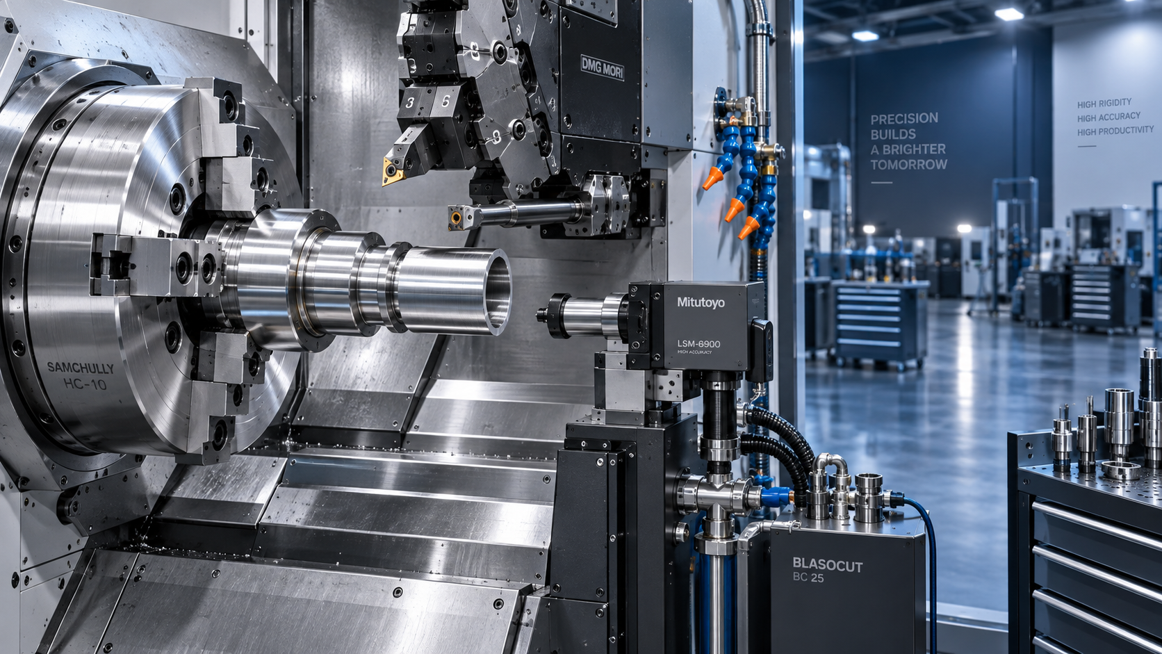
 How to Select a CNC Metal Lathe for Tight-Tolerance Shaft and Sleeve PartsCNC Machining Technology Center
 How to Select an Industrial Lathe for High-Volume Shaft ProductionMachine Tool Industry Editorial Team
 Selecting Machine Tools for Automotive Parts: Accuracy, Throughput, and AutomationMachine Tool Industry Editorial Team
 Industrial Machining: Selecting Processes for Tight-Tolerance Metal PartsCNC Machining Technology Center

Aris Katos
Future of Carbide Coatings
15+ years in precision manufacturing systems. Specialized in high-speed milling and aerospace grade alloy processing.
▶
How to Cut CNC Machining Energy Use per Part Without Longer Cycle TimesCNC Machining Technology Center▶
Is Learning CNC Programming Worth It for Shop Owners Seeking Higher Margins?CNC Machining Technology Center▶
How to Select CNC Equipment for High-Mix, Low-Volume ProductionCNC Machining Technology Center▶
Can CNC Machining Inconel Control Tool Wear in High-Temperature Aerospace Parts?CNC Machining Technology Center▶
How Automated Precision Machining Maintains Tolerance in High-Mix ProductionCNC Machining Technology Center
Mastering 5-Axis Workholding Strategies
Join our technical panel on Nov 15th to learn about reducing vibrations in thin-wall components.

Providing you with integrated sanding solutions
Before-sales and after-sales services
Comprehensive technical support