• Global CNC market projected to reach $128B by 2028 • New EU trade regulations for precision tooling components • Aerospace deman
NYSE: CNC +1.2%LME: STEEL -0.4%

How Multi-axis Machining Systems for Aerospace Improve Accuracy on Complex Parts
Why Complex Aerospace Parts Push Accuracy Demands Higher
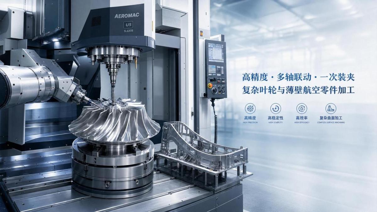
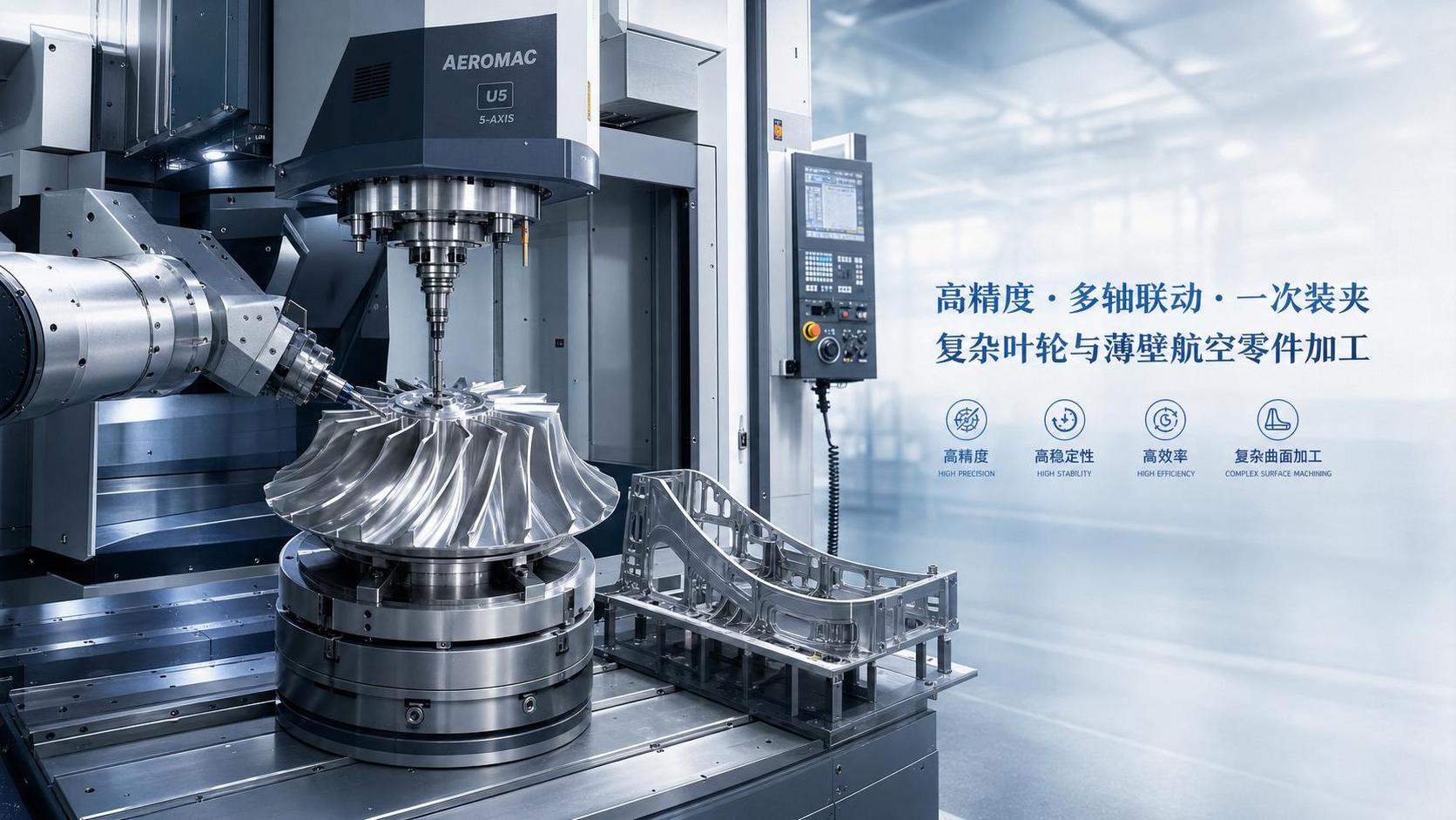
A Multi-axis Machining System for Aerospace matters most when part geometry stops being simple and tolerance windows stop being forgiving.
In aerospace production, accuracy is not only about hitting one dimension on a drawing.
It also affects surface integrity, assembly fit, fatigue life, and the repeatability of every downstream process.
That is why multi-axis capability has moved from a niche advantage to a practical requirement in many precision manufacturing environments.
Across the global CNC machine tool industry, the shift toward higher precision, automation, and digital integration has made this even more visible.
Aerospace applications sit at the sharp end of that shift because structural parts, engine components, and lightweight assemblies combine complexity with strict process control.
A well-matched Multi-axis Machining System for Aerospace reduces setups, keeps tool engagement more stable, and limits the cumulative error that appears when parts are repositioned too often.
The real question is not whether multi-axis machining improves accuracy, but under which operating conditions the improvement becomes decisive.
Actual shop conditions change what accuracy really means
Different aerospace parts fail for different reasons, so the judging logic cannot stay the same across every job.
Thin-wall housings are sensitive to vibration and heat distortion.
Blisks and impellers are more affected by tool orientation, surface continuity, and blade-to-blade consistency.
Large structural components often expose issues in machine stiffness, travel stability, and thermal compensation over long cycles.
In actual use, the better approach is to connect part features with process risk.
If the main risk comes from repositioning error, fewer setups will usually deliver the biggest gain.
If the risk comes from chatter or uneven cutting load, spindle behavior, axis synchronization, and fixture strategy deserve more attention.
This is where a Multi-axis Machining System for Aerospace differs from a standard machining center.
It is not just adding more motion axes.
It is creating more effective tool access while protecting dimensional control on difficult surfaces.
When contoured blades and flow surfaces are involved
Blade-like parts are one of the clearest cases where a Multi-axis Machining System for Aerospace improves accuracy in a measurable way.
These geometries require smooth transitions, consistent profile control, and stable scallop height across curved surfaces.
With fewer angular compromises, the tool can stay closer to the ideal cutting direction.
That lowers tool deflection and reduces the small deviations that later become aerodynamic or balancing problems.
A common mistake here is focusing only on simultaneous axis count.
For this kind of work, interpolation quality, control response, and CAM strategy often matter just as much as the machine layout itself.
If blade profiles vary after heat generation rises, the issue may come from thermal drift, not from nominal axis precision.
That is why process simulation, dynamic testing, and trial cutting remain practical checkpoints before drawing conclusions.
Thin-wall structures need stability more than headline speed
A different pattern appears in ribs, frames, brackets, and lightweight housings.
These parts are easy to distort, even when the programmed dimensions look conservative.
Here, a Multi-axis Machining System for Aerospace helps by allowing better access angles and shorter tool overhang.
That usually translates into less chatter, better wall consistency, and improved flatness after unclamping.
More importantly, the system can support machining sequences that spread stress more evenly across the part.
In this scenario, pure feed rate comparisons can be misleading.
A faster cycle that creates rework or dimensional drift is rarely the better result.
The more useful judgment points are fixture accessibility, cut balance, coolant delivery, and the machine’s ability to maintain repeatability during long finishing passes.
Large structural parts expose the full machine ecosystem
Accuracy challenges become broader when the workpiece is large enough to amplify every weakness in the process chain.
For spars, panels, and structural nodes, the Multi-axis Machining System for Aerospace is only one part of the answer.
The rest includes fixture design, probing routines, thermal monitoring, tool management, and software compensation.
In these jobs, fewer setups still matter, but long travel accuracy and machine geometry retention become equally important.
This is also where digital integration earns real value.
Closed-loop measurement, tool life tracking, and in-process verification can prevent small offsets from growing into expensive scrap.
Global machine tool suppliers increasingly position these capabilities together because large aerospace parts rarely reward isolated equipment decisions.
The judging points are not the same across part families
A side-by-side view makes the differences easier to manage during evaluation.
This is why one specification sheet rarely explains the full fit.
The same Multi-axis Machining System for Aerospace can perform very differently depending on part scale, material response, and process discipline around it.
Where evaluation often goes wrong before implementation
Several misjudgments appear repeatedly when comparing aerospace machining options.
- Looking at static accuracy numbers without checking dynamic cutting behavior.
- Assuming similar titanium and aluminum parts need the same spindle and rigidity balance.
- Treating fixture access as a secondary issue, even when it drives deformation risk.
- Comparing purchase cost without including calibration, tooling, software, and maintenance demands.
- Ignoring how automation, probing, and data feedback affect long-run consistency.
In practice, these mistakes narrow the decision too early.
A Multi-axis Machining System for Aerospace should be judged as part of a process environment, not as a standalone machine body.
How to match the system to the aerospace job more effectively
A useful next step is to build the evaluation around actual part families and process limits.
Start with the features that most often trigger nonconformance.
Then trace whether those failures come from setup transfer, thermal growth, vibration, or poor tool approach.
From there, the fit becomes easier to verify.
- Group parts by geometry risk, not only by material or size.
- Define acceptable variation for profile, position, finish, and post-clamp distortion.
- Test the Multi-axis Machining System for Aerospace with representative toolpaths, not generic demos.
- Review fixture, toolholder, coolant, and software support together.
- Check maintenance intervals and recalibration needs before scaling production.
The broader manufacturing trend toward smart factories and flexible production lines reinforces this approach.
Accuracy gains are strongest when machine capability, process control, and digital feedback are aligned around the same aerospace workload.
For any operation comparing options, the practical path is clear.
Map the real application scenario, confirm the limiting features, compare long-cycle stability, and weigh implementation effort alongside tolerance targets.
That is usually the point where the right Multi-axis Machining System for Aerospace becomes easier to identify, and the accuracy advantage becomes easier to sustain.
Recommended for You
 How to Select a CNC Metal Lathe for Tight-Tolerance Shaft and Sleeve PartsCNC Machining Technology Center
 How to Select an Industrial Lathe for High-Volume Shaft ProductionMachine Tool Industry Editorial Team
 Selecting Machine Tools for Automotive Parts: Accuracy, Throughput, and AutomationMachine Tool Industry Editorial Team
 Industrial Machining: Selecting Processes for Tight-Tolerance Metal PartsCNC Machining Technology Center
 Manufacturing Technology Trends That Improve Throughput and Quality ControlManufacturing Market Research Center
 How to Design Cost-Effective Fixtures That Maintain Cycle Time in Mass ProductionCNC Machining Technology Center

Aris Katos
Future of Carbide Coatings
15+ years in precision manufacturing systems. Specialized in high-speed milling and aerospace grade alloy processing.
▶
Is Learning CNC Programming Worth It for Shop Owners Seeking Higher Margins?CNC Machining Technology Center▶
How to Select CNC Equipment for High-Mix, Low-Volume ProductionCNC Machining Technology Center▶
Can CNC Machining Inconel Control Tool Wear in High-Temperature Aerospace Parts?CNC Machining Technology Center▶
How Automated Precision Machining Maintains Tolerance in High-Mix ProductionCNC Machining Technology Center▶
CNC Programming Explained: From CAD Models to Reliable Shop-Floor ToolpathsCNC Machining Technology Center
Mastering 5-Axis Workholding Strategies
Join our technical panel on Nov 15th to learn about reducing vibrations in thin-wall components.

Providing you with integrated sanding solutions
Before-sales and after-sales services
Comprehensive technical support