• Global CNC market projected to reach $128B by 2028 • New EU trade regulations for precision tooling components • Aerospace deman
NYSE: CNC +1.2%LME: STEEL -0.4%

Why Heavy Machinery Shafts Fail Under Cyclic Loads and How to Prevent It
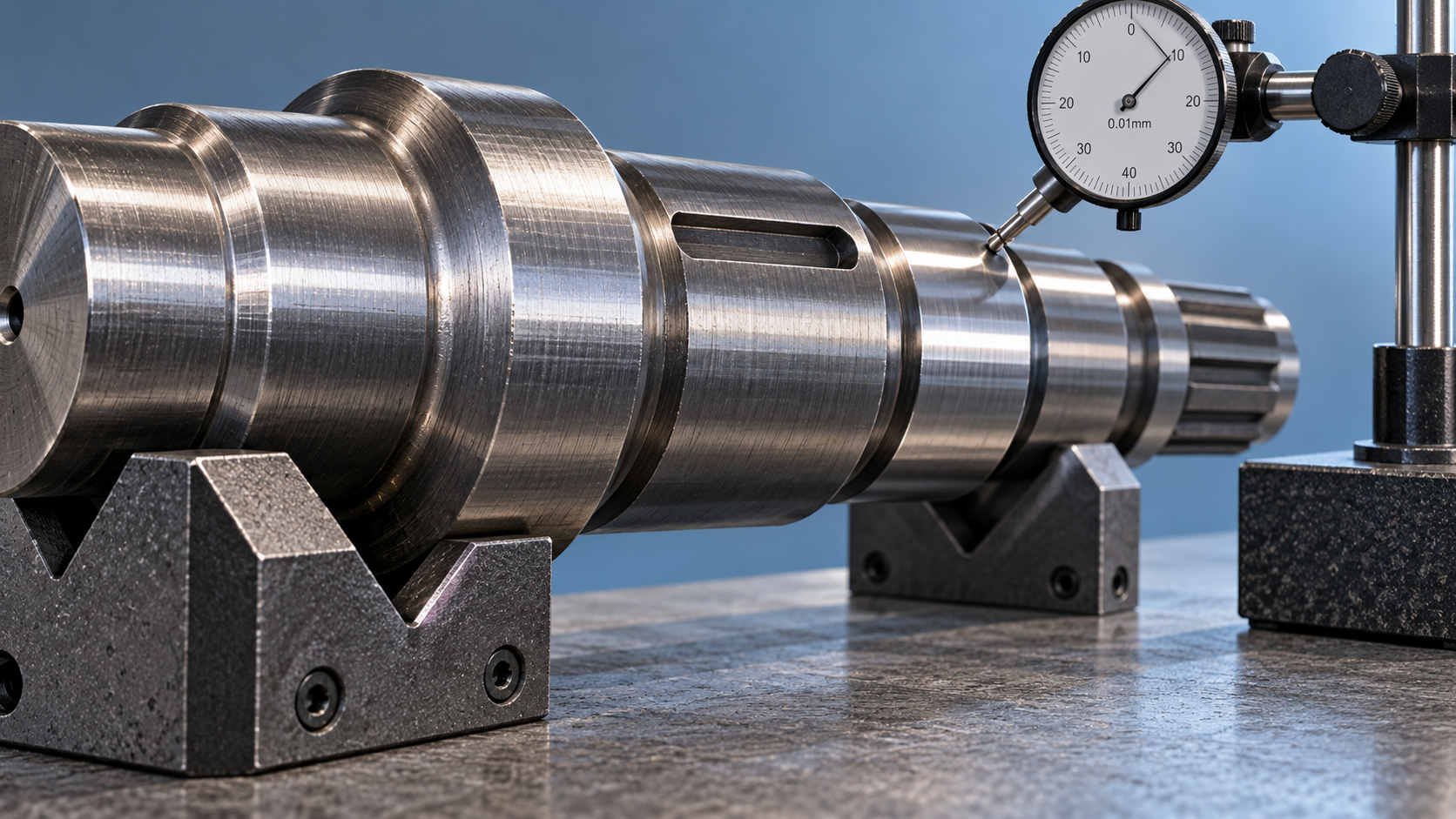
A heavy machinery shaft can crack even when its operating load remains below the material’s static strength limit. Repeated bending and twisting can grow a small defect at a keyway, shoulder, or bearing seat until the remaining section breaks. The result may be an unexpected shutdown, damaged bearings, and a replacement shaft that fails again because the original loading problem remains.
Preventing repeat failures requires controlling local cyclic stress, not simply installing a stronger shaft. For Shaft Parts for Heavy Machinery, the practical starting point is to preserve fracture evidence, verify alignment and support conditions, and check whether geometry, surface damage, or material condition has reduced fatigue resistance.
Why normal operating loads can still cause fatigue
A rotating shaft carrying a steady transverse load can experience alternating bending stress. As a point on its surface rotates through the loaded region, it moves between tension and compression. The external force may look constant, but the material experiences repeated stress cycles. Torque fluctuations from starts, reversals, jams, or changing process resistance add another cyclic component.
Fatigue commonly begins where local stress exceeds what a nominal shaft calculation suggests. A sharp shoulder, keyway corner, corrosion pit, or machining groove concentrates stress. Once a crack develops, its tip becomes another stress concentration, allowing growth under repeated loading without obvious permanent deformation.
Stress amplitude, mean stress, cycle count, and the operating environment all influence life. Occasional overloads may accelerate damage even when average operating torque appears acceptable. A fatigue assessment therefore needs the actual duty cycle, including starts and transient events, rather than motor power or rated torque alone.
Preserve the evidence before replacing the shaft
Before inspection, isolate and lock out the machine, release stored energy, and support components that could rotate or drop. Do not run equipment with a suspected shaft crack simply to collect more vibration data. A fracture can also leave gears, pulleys, or couplings inadequately supported.
Photograph the shaft in position before dismantling. Record the fracture’s location relative to bearings, shoulders, keyways, and driven components. Mark component orientation away from the fracture surface. Keep both broken pieces, and avoid grinding, wire brushing, or fitting the fracture faces together, which can destroy evidence.
Collect operating information while it is still available: load changes, trips, reversals, unusual noise, bearing temperature trends, and previous repairs. A replacement that repeatedly fails at the same shoulder points toward a persistent local stress or support problem, but the fracture and installation measurements must confirm that hypothesis.
Read the fracture without treating appearance as proof
A fatigue fracture may contain a relatively smooth propagation region and a rougher final overload region. Visible arrest marks can suggest progressive crack growth, while several surface origins may indicate multiple initiation sites. Their absence does not rule out fatigue; corrosion, rubbing after fracture, and surface contamination can obscure the pattern.
The apparent origin is particularly useful when compared with nearby features. A crack starting at a keyway end suggests a different investigation from one starting beneath a bearing seat. Fracture angle alone is not a reliable way to separate bending from torsion, especially under combined loading.
For costly, recurring, or safety-critical failures, preserve the parts for metallurgical examination. Fractography, metallography, hardness testing, and material verification can distinguish surface initiation from internal defects and assess possible heat-treatment problems. Visual inspection alone cannot establish steel grade or heat-treatment quality.
Find the source of damaging cyclic stress
Misalignment and support movement
Coupling misalignment introduces loads that the shaft may not have been designed to carry continuously. Check angular and offset alignment using the machine manufacturer’s procedure, including specified thermal-growth targets. A flexible coupling accommodates limited movement; it does not make poor alignment harmless.
Inspect soft foot, loose foundation bolts, housing distortion, and worn bearing seats before correcting coupling position. Otherwise, tightening the assembly or reaching operating temperature may change the alignment again. Where practical, compare cold measurements with approved operating-condition checks.
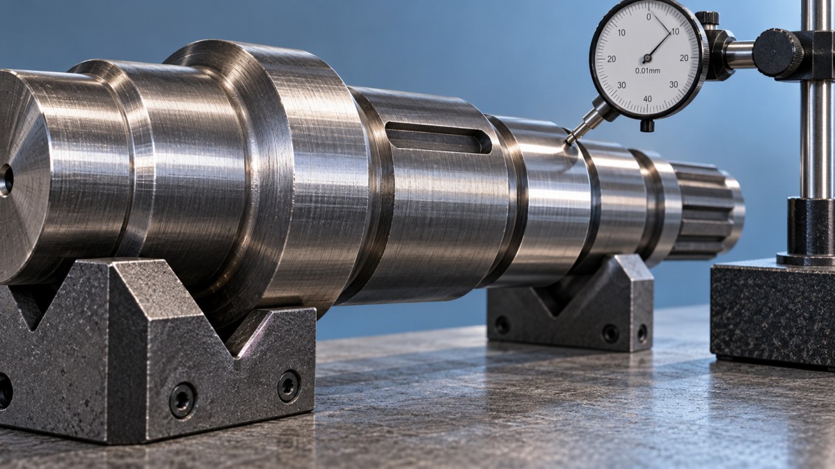
Runout also needs careful interpretation. A high reading at one location may come from shaft bending, an eccentric surface, debris under a fitted component, or measurement setup error. Measure at defined reference surfaces and compare results with drawing or manufacturer limits rather than applying a universal tolerance.
Overhung loads and changing torque
A pulley, sprocket, or gear mounted beyond the nearest bearing increases bending at the adjacent shaft section. Excessive belt tension, an offset load path, or an unauthorized component change can worsen it. Verify mounting position, belt tension, and bearing spacing against the approved arrangement.
Review how the machine starts and stops. Abrupt engagement, backlash take-up, stalled material, and repeated reversing can produce short torque peaks that ordinary trend displays miss. Capturing those peaks may require suitable drive logging or temporary instrumentation selected by an engineer. Average motor current alone is not a complete record of shaft stress.
Check the replacement beyond its material grade
Installing higher-strength steel does not automatically solve fatigue. A sharp notch, unsuitable heat treatment, or damaged surface can offset the benefit. Some higher-strength materials are more notch-sensitive, and hardness changes can affect toughness. Select a replacement against the approved design requirements, not a “stronger is better” rule.
Critical checks for a machined replacement include:
- Shoulder and keyway geometry: Verify specified radii, corner relief, keyway depth, and end shape. Check that mating bearing or hub chamfers clear the shaft fillet.
- Surface condition: Inspect highly stressed transitions and fits for tool marks, chatter, grinding damage, dents, corrosion, and unauthorized blending.
- Dimensional relationships: Confirm bearing-seat size, roundness, concentricity, and relevant runout. Correct diameters do not guarantee an acceptable assembled load path.
- Material and heat treatment: Review traceable documentation and specified inspection results. Use additional verification where records are incomplete or findings conflict.
CNC machining can reproduce complex shaft geometry accurately, but fatigue performance also depends on process control. Tool wear, poor deburring, grinding heat, and inadequate inspection can leave defects at critical locations. Surface roughness values alone do not describe every damaging scratch or metallurgical condition.
Do not enlarge fillets, change keyways, increase interference, or add surface treatments as an informal repair. These changes can interfere with mating parts or alter stress distribution. Shot peening, nitriding, and induction hardening may improve fatigue resistance in suitable designs, but each requires controlled parameters and engineering approval.
Inspect damage with the right method
Visual inspection is useful for locating corrosion, fretting, and obvious cracks, but it cannot clear a shaft for continued service by itself. Inspection method, surface preparation, coverage, and acceptance criteria should match the material, geometry, and expected defect location.
Magnetic particle testing is suitable for surface and some near-surface discontinuities in ferromagnetic shafts. Dye penetrant testing can reveal surface-breaking defects on suitable nonporous materials, but coatings, contamination, and smeared metal can conceal indications. Ultrasonic testing may help assess internal defects or selected crack locations, although geometry and near-surface limitations affect coverage.
Use qualified inspection personnel and an approved procedure for critical shafts. A report stating “no indications” is meaningful only within the method’s sensitivity and inspected area. It is not a remaining-life prediction. A confirmed crack requires disposition under the applicable engineering procedure, not a trial return to service.
Install without adding a new fatigue starter
Assembly damage can undo an otherwise sound replacement. Clean mating surfaces and inspect bearing bores, hubs, keys, and locking components. Remove only permitted raised burrs using the approved method; do not file a shaft seat until a tight component fits.
- Verify fits before assembly. Measure shaft and mating-part dimensions, then compare them with specified fits and inspection temperatures.
- Use the prescribed mounting method. Avoid hammer blows through bearings or against shaft ends. Apply mounting force through the correct bearing ring, and use controlled heating where specified.
- Check keys and axial location. Confirm key fit, hub seating, spacers, shoulders, and locking arrangements. A proud key can prevent correct hub contact.
- Align the complete assembly. Correct support problems first, then set coupling alignment, belt tension, and other external loads.
- Record commissioning measurements. Establish vibration, temperature, and relevant load baselines under documented operating conditions.
During the approved staged restart, investigate abnormal vibration, rubbing, unstable temperature, or unexpected drive load before increasing duty. Compare measurements at equivalent speed and load; otherwise, normal operating changes can be mistaken for deterioration or improvement.
Decide what must change before returning to full duty
The corrective action should match the evidence. A machining defect calls for manufacturing correction and inspection of related stock. Fretting at a hub requires review of fit, contact, and relative movement. Recurrent shoulder cracking with sound material may require a design review of fillet geometry, bearing position, or overhung loading rather than another identical replacement.
Set follow-up inspections according to the failure mechanism and consequence, not an arbitrary calendar interval. Vibration monitoring can reveal bearing or alignment problems, but it may not provide dependable early warning of every shaft crack. Direct crack inspection may therefore be necessary at selected locations.
Where loads remain uncertain, the fracture recurs, or continued operation has serious safety consequences, an engineering assessment should define acceptable duty and inspection requirements before restart. Retain the fracture findings, alignment results, component measurements, and corrective actions in the service record so the next maintenance decision is based on the actual failure mechanism.
NEXT ARTICLE
Recommended for You
![]() AI Investment Lifts US September Equipment Demand; Core Capital Goods Orders Rise 0.5%Manufacturing Market Research Center
 Why Heavy Machinery Shafts Fail Under Cyclic Loads and How to Prevent ItCNC Machining Technology Center
![]() JTEKT Introduces G5 Series Large CNC Cylindrical Grinder, Sales Begin October 26, 2026Machine Tool Industry Editorial Team
 Shaft Parts for Heavy Machinery: Selecting Materials for High Shock LoadsCNC Machining Technology Center
![]() 33rd JIMTOF 2026 Set to Open in Tokyo as Taiwanese Exhibitors Seek OrdersGlobal Machine Tool Trade Research Center
 Which Fixture Type Cuts Changeover Time Most in High-Mix CNC Machining?CNC Machining Technology Center


Aris Katos
Future of Carbide Coatings
15+ years in precision manufacturing systems. Specialized in high-speed milling and aerospace grade alloy processing.
▶
Why Heavy Machinery Shafts Fail Under Cyclic Loads and How to Prevent ItCNC Machining Technology Center▶
Shaft Parts for Heavy Machinery: Selecting Materials for High Shock LoadsCNC Machining Technology Center▶
What Is Metal Processing? From Raw Material to Finished Machine PartsCNC Machining Technology Center▶
How long does CNC machine delivery and installation usually take?CNC Machining Technology Center▶
CNC Machine Arrival Inspection: Check Shipping Damage, Accuracy, Safety, and DocumentsCNC Machining Technology Center
▶
Mastering 5-Axis Workholding Strategies
Join our technical panel on Nov 15th to learn about reducing vibrations in thin-wall components.

Providing you with integrated sanding solutions
Before-sales and after-sales services
Comprehensive technical support