• Global CNC market projected to reach $128B by 2028 • New EU trade regulations for precision tooling components • Aerospace deman
NYSE: CNC +1.2%LME: STEEL -0.4%

CNC Machine Arrival Inspection: Check Shipping Damage, Accuracy, Safety, and Documents
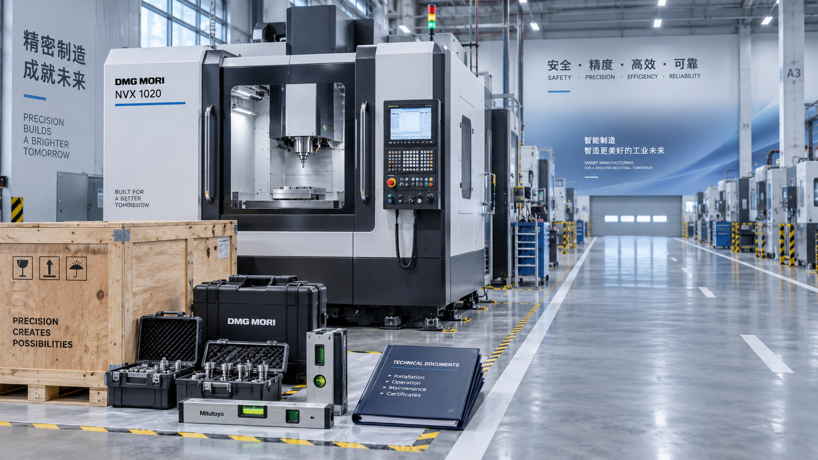
Inspect Before You Accept the Machine
A CNC machine can arrive looking intact while carrying damage or installation issues that only become visible after power-up, alignment, or the first accuracy test. For quality and safety teams, the receiving inspection is therefore more than a delivery check: it is the point at which transport responsibility, equipment condition, and commissioning readiness are documented.
When asking what should I check when a CNC machine arrives at factory, the practical answer is to inspect in stages and avoid signing final acceptance too early. Confirm the external condition before unloading, verify the machine and accessories against shipping records, then establish a documented baseline for safety and performance before the equipment enters production.
Start With the Delivery Condition, Before Packaging Is Removed
The first inspection should happen while the machine is still on the carrier or immediately after unloading, with the freight documents available. A damaged crate, broken banding, punctured protective wrap, shifted blocking, water staining, or a tilted shock indicator does not prove that the machine is damaged, but it creates a reason to record the condition and inspect more deeply.
Photograph the shipment from several angles before opening it. Include container or truck condition where relevant, package labels, shock or tilt indicators, visible impact points, and the machine serial-number plate once accessible. Time-stamped photographs are useful if responsibility later has to be discussed with the carrier, insurer, supplier, or installation contractor.
- Compare the number of packages, crates, pallets, and loose items with the packing list.
- Check that shipping labels, machine model, serial number, and destination details match the purchase and delivery documents.
- Look for water ingress, corrosion, torn vapor barrier material, or damaged desiccant packaging, especially after long-distance transport.
- Record any evidence that lifting points, forklift pockets, skids, or base supports were mishandled.
- Do not discard damaged packaging until the condition has been documented and any claim process is clear.
For large machining centers, lathes, and multi-axis equipment, lifting damage can be as important as an external impact. Incorrect sling position or fork placement may affect guarding, chip conveyors, cabinet doors, coolant assemblies, workholding components, or the machine base. A machine should be lifted only according to the manufacturer’s handling instructions; arrival inspection should verify that those instructions are present and that the unloading method has not introduced a new risk.
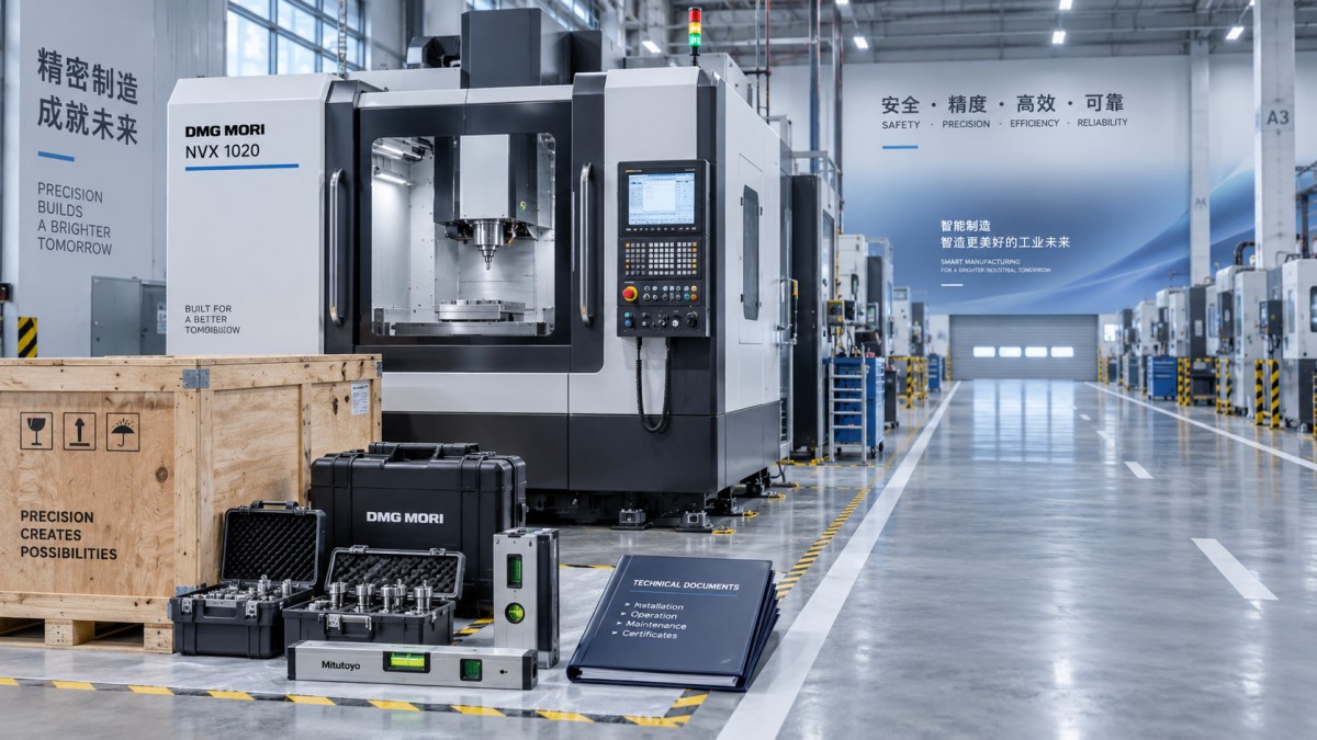
Check Completeness Against the Packing List, Not Memory
Receiving teams often focus on the main machine and discover later that a probe, transformer, hydraulic unit, tool magazine component, electrical cabinet accessory, or installation kit is missing. That can delay commissioning even when the machine itself is undamaged.
Use the packing list as a controlled verification document. Separate items into machine body, standard accessories, optional equipment, tooling and fixtures, utility connections, software or controller media, documentation, and spare parts. Count loose items and identify their storage location. Small components should not be accepted as “probably inside the machine” unless their location is confirmed.
Pay particular attention to shipment-specific equipment that may be needed before first operation:
- Leveling pads, anchor hardware, shims, and foundation-related parts.
- Electrical cables, plugs, transformers, grounding components, and interface connectors.
- Hydraulic, pneumatic, coolant, lubrication, and chip-management accessories.
- Toolholders, pull studs, collets, jaws, chucks, fixtures, probes, and calibration artifacts when supplied.
- Safety guards, interlocks, light curtains, manuals, keys, and controller access credentials.
A missing optional item should be recorded separately from transport damage. Combining the two issues in a vague receiving note makes later resolution harder because the corrective actions, evidence, and responsible parties may differ.
Inspect the Machine for Transport Restraints, Leaks, and Mechanical Damage
Before energizing the machine, inspect exposed surfaces and accessible internal areas. The purpose is not to perform a full service inspection, but to identify conditions that could make power-up unsafe or compromise accuracy.
Look for cracked covers, distorted sheet metal, damaged windows, broken cable carriers, loose connectors, bent handles, damaged guideway covers, and displaced enclosures. Open panels only where the manufacturer permits and where trained personnel can do so safely. Electrical cabinets should remain isolated until their internal condition, supply requirements, and grounding arrangements have been reviewed.
Transport brackets, spindle locks, axis restraints, counterweight restraints, and other shipping devices deserve particular attention. They are installed to protect the machine during transport, yet operating the machine before they are removed can cause serious damage. Conversely, removing restraints prematurely can be unsafe when the machine is not correctly supported or leveled. Follow the manufacturer’s sequence and retain removed parts where the manual requires them for future relocation.
Check for oil, coolant, hydraulic fluid, grease, or lubricant leakage. A small amount of protective oil may be normal after shipment, but pooling beneath the machine, wet electrical areas, damaged hoses, or an empty fluid reservoir should trigger investigation before start-up. Leaks can indicate a fractured fitting, loose connection, damaged seal, or transport movement beyond the machine’s intended limits.
Safety Verification Comes Before Functional Testing
A CNC machine cannot be treated as ready because the control screen powers on. Before initial energization, verify that the site utilities and safety conditions match the manufacturer’s installation requirements. This includes electrical supply characteristics, protective grounding, isolation capability, air supply where required, hydraulic or coolant arrangements, floor loading, clearance for maintenance, and adequate access around moving parts.
The safety review should identify hazards created by the installation itself. Examples include an inaccessible emergency stop, inadequate clearance for opening an electrical cabinet, a chip conveyor discharge point creating a trip hazard, unprotected cable routing, or a machine placed where lifting and service work cannot be carried out safely.
Safety functions should be tested during controlled commissioning, not bypassed to save time. A door interlock that prevents an early motion test may be inconvenient, but defeating it removes an important opportunity to identify wiring, parameter, or installation defects.
Establish an Accuracy Baseline After Proper Installation
Arrival acceptance and final performance acceptance are related but different steps. External damage and completeness can be checked at delivery; geometric accuracy cannot be judged reliably while a machine is still on shipping supports, inadequately leveled, thermally unstable, or operated with unverified utilities.
After installation and stabilization, quality personnel should work from the purchase specification, manufacturer acceptance procedure, and applicable internal quality requirements. The test method must match the machine type and the work it is expected to perform. A machining center, turning center, and multi-axis system do not present the same accuracy risks.
Common baseline checks can include axis travel and direction, spindle operation, repeatability, backlash-related behavior, positioning performance, geometric relationships, and the correct operation of probing or tool-setting systems when included. Test cuts may be appropriate, but a single acceptable part is not enough evidence of machine capability. Thermal condition, tooling quality, fixture rigidity, program strategy, and operator setup can all influence the result.
For equipment intended for tight-tolerance work, keep the as-installed test records with the machine file. They provide a reference when later problems arise after collision, relocation, repair, unusual wear, or process changes. The objective is to distinguish an original acceptance condition from a later degradation.
Documents Are Part of the Equipment Handover
A machine without complete documentation is difficult to operate, maintain, validate, or audit safely. The document package should be checked at arrival and completed before the machine is released for normal production.
- Commercial documents: purchase order, packing list, delivery note, invoice where relevant, and serial-number records.
- Technical documents: installation instructions, operation manual, maintenance manual, lubrication schedule, electrical diagrams, pneumatic and hydraulic diagrams where applicable.
- Acceptance records: factory acceptance information when supplied, installation and commissioning reports, accuracy test records, and any agreed inspection protocol.
- Safety information: risk-related instructions, warning labels, emergency procedures, declarations or conformity documents where required for the installation jurisdiction.
- Control and software information: controller backup arrangements, parameter records, license details, communication settings, and recovery procedures.
Document control matters because the machine’s configuration can differ from a catalogue description or an earlier quotation. Optional axes, guarding, automation interfaces, electrical ratings, spindle configuration, and software features should be confirmed against the delivered serial-numbered machine rather than assumed from a general product manual.
Use a Clear Acceptance Status
The receiving record should not force a false choice between “accepted” and “rejected.” A more useful approach is to distinguish physical receipt from final technical acceptance. A machine may be received with exceptions, held pending inspection, or accepted for installation while specific missing items or damage claims remain open.
List each nonconformance precisely: the affected component, location, supporting photo or document reference, observed condition, date, and required follow-up. Avoid vague statements such as “machine damaged” or “accessories incomplete.” Clear records allow the supplier and carrier to respond to a defined issue, while the factory maintains control over whether commissioning can proceed.
The final release should follow evidence, not delivery pressure. Once shipping condition, completeness, safe installation, required documents, and agreed baseline checks have been addressed, the machine can enter production with a documented starting point rather than an unresolved uncertainty.
PREVIOUS ARTICLE
NEXT ARTICLE
Recommended for You
 CNC Machine Arrival Inspection: Check Shipping Damage, Accuracy, Safety, and DocumentsCNC Machining Technology Center
 How to Select a Machine Tool for Aerospace Parts with Tight Tolerances?Machine Tool Industry Editorial Team
 How to Select CNC Equipment for High-Mix, Low-Volume ProductionCNC Machining Technology Center
 Can CNC Machining Inconel Control Tool Wear in High-Temperature Aerospace Parts?CNC Machining Technology Center
 Machine Tool Market Outlook: Demand Drivers, Capacity Shifts, and Investment RisksManufacturing Market Research Center
 Zero-Point Clamping or Modular Fixtures? Choosing a Faster CNC Changeover SystemCNC Machining Technology Center



Aris Katos
Future of Carbide Coatings
15+ years in precision manufacturing systems. Specialized in high-speed milling and aerospace grade alloy processing.
▶
CNC Machine Arrival Inspection: Check Shipping Damage, Accuracy, Safety, and DocumentsCNC Machining Technology Center▶
What Should You Check When a CNC Machine Arrives at Your Factory?CNC Machining Technology Center▶
What Safety Checks Are Required for CNC Cutting Operations?CNC Machining Technology Center▶
What Are Machine Tools? Common Types, Functions, and Typical Shop ApplicationsCNC Machining Technology Center▶
CNC Industrial Machines Maintenance Checklist: How to Reduce Downtime and Tool WearCNC Machining Technology Center
Mastering 5-Axis Workholding Strategies
Join our technical panel on Nov 15th to learn about reducing vibrations in thin-wall components.

Providing you with integrated sanding solutions
Before-sales and after-sales services
Comprehensive technical support