• Global CNC market projected to reach $128B by 2028 • New EU trade regulations for precision tooling components • Aerospace deman
NYSE: CNC +1.2%LME: STEEL -0.4%

How to Design Cost-Effective Fixtures That Maintain Cycle Time in Mass Production
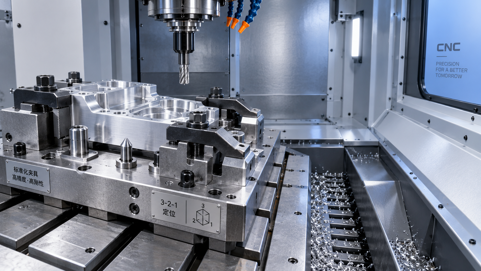
On a high-volume CNC line, fixture cost is often reviewed as a separate tooling expense while cycle time is treated as a machining problem. That separation causes trouble. A lower-priced fixture can add seconds at every load, force an operator to reposition parts twice, limit chip evacuation, or require cautious clamping to prevent distortion. Across thousands of cycles, those small losses can outweigh the saving made at purchase.
The practical answer is to design only the fixture features that protect part location, clamp stability, access, and handling speed. Cost-effective fixture design for mass production does not mean using the fewest components at any price. It means spending money where variation or delay would recur on every cycle, while simplifying features that do not improve repeatability, safety, or takt time. Start from the real work sequence—load, locate, clamp, machine, unclamp, unload—not from a preferred fixture style.
Begin with the production cycle, not the fixture drawing
Before selecting locators, cylinders, or baseplate material, map the operator and machine actions in the actual order they occur. A fixture that holds the part securely may still be unsuitable if the operator must reach around a clamp, rotate a component to find a datum, clear chips manually, or wait for a clamp to return before unloading.
For each operation, identify four time elements:
- Part presentation: how the workpiece reaches the fixture and whether its orientation is controlled before loading.
- Location: how many movements are needed before the part reaches its defined datums.
- Clamping: whether clamp engagement is immediate, visible, and repeatable without adjustment.
- Release and removal: whether the finished part can be removed without sticking, catching on locators, or contacting sharp edges.
This review often reveals that an elaborate fixture is compensating for an upstream handling issue. For example, adding multiple adjustable supports may seem necessary when a casting arrives inconsistently oriented. But a simple loading nest or poka-yoke feature at the presentation point may eliminate the need for those adjustments. Likewise, a part that must be manually held while a clamp closes may need a better rest pad arrangement, not a stronger clamp.
Cycle time should be separated into machine-cutting time and non-cutting fixture-related time. Cutting time may be fixed by toolpath and material removal requirements. Fixture-related time is usually more open to improvement, especially where loading and clamping happen while the spindle is idle. The goal is not merely a fast clamp; it is a fast, mistake-resistant sequence.
Define the locating scheme before choosing clamps
A low-cost fixture becomes expensive when it relies on clamps to establish position. Clamps should force the workpiece against established locating points; they should not be expected to find the part’s correct X, Y, and Z position. When locating and clamping are mixed together, part variation, burrs, operator technique, and clamp wear begin to affect machining position.
The 3-2-1 principle remains useful, but it must be applied to the part’s functional datums rather than copied as a generic pattern. Use primary supports to establish the main plane, secondary locators to control sideways movement, and a tertiary stop to set final axial position. Then verify that the chosen contact points are stable, accessible, and not located on surfaces likely to carry scale, flash, or machining burrs.
Choose datum surfaces that survive production reality
Nominally flat surfaces are not always reliable fixture datums. Raw castings may have draft and surface variation. Forged surfaces can have scale. A thin machined wall may flex under clamp force. If the fixture references such areas, the inspection result may look inconsistent even when the machine is performing correctly.
More dependable approaches include using a pre-machined feature created in an earlier operation, locating on robust bosses, or using hardened pins in deliberately selected holes. Where a feature must accept dimensional variation, use one round locating pin and one relieved diamond pin rather than two tight round pins. This controls position while preventing the fixture from fighting normal part tolerance or thermal expansion.
Keep the locator count disciplined. Extra pins and pads are often added to make a fixture appear more secure, but they can create overconstraint. A part may rock between contact points, sit differently after chip contamination, or require force to seat. Three well-positioned primary supports are normally more reliable than a crowded field of supports with uncertain contact.
Reduce fixture cost by standardizing what does not define the part
The most economical fixture is rarely a completely custom assembly. It uses custom components only where the workpiece geometry demands them and relies on standard elements everywhere else. Baseplates, toggle clamps, hydraulic swing clamps, rest buttons, dowel pins, bushings, bolts, handles, and modular risers can often be standardized across related operations.
Standardization lowers more than initial manufacturing cost. It simplifies spare-part management, shortens maintenance work, and makes troubleshooting easier for production teams. A damaged locator pin can be replaced quickly when its size, mounting method, and material are already defined. A unique formed clamp arm may be justified where access is restricted, but it should not become the default choice merely because it looks tailored to the part.
A useful design question is: “What function would be lost if this custom feature became a standard part?” If the answer is only appearance, convenience during assembly, or a theoretical stiffness increase that does not affect the process, it is a candidate for simplification.
Make loading intuitive without adding unnecessary mechanisms
Fast loading depends on orientation certainty. The operator should be able to place the part into the fixture with a short, natural motion and receive immediate physical confirmation that it is seated. Deep nests, narrow pin clearances, hidden stops, and clamp handles positioned behind the part slow this action and increase the chance of incomplete seating.
Where part geometry allows, use asymmetry deliberately. A single offset pin, relief pocket, shaped stop, or asymmetric nest can prevent reverse loading without sensors or complex interlocks. Such poka-yoke features are generally less expensive and more reliable than asking operators to inspect orientation visually at each cycle.
However, avoid making the workpiece difficult to remove in the pursuit of positive location. Tight nests can trap coolant, chips, or vacuum effects. Provide adequate clearance around non-locating surfaces and include a controlled release path. A small ejector, spring plunger, air blast, or angled relief may be justified when parts routinely stick after machining. The right choice depends on part mass, surface finish requirements, coolant use, and automation plans. A release feature should assist removal, not push the part away before clamps have fully opened.
Manual, pneumatic, and hydraulic clamping have different cost logic
Manual toggle clamps are economical when loading frequency is moderate, clamp force is repeatable enough, and the operator can engage them in one motion without crossing the machine opening. They are also easy to maintain. Their weakness appears when several clamps must be operated in sequence, when force consistency is critical, or when an automated cell is planned.
Pneumatic clamping can reduce handling effort and support simple automation, but air compressibility may make it less suitable where rigid, highly repeatable holding force is required. Hydraulic clamping offers high force in a compact layout and can coordinate multiple clamps, but it introduces plumbing, leakage control, power-unit requirements, and maintenance considerations. The more expensive system is not automatically faster if it adds a long confirmation sequence or forces a complex manifold layout.
Choose clamp actuation by reviewing the required force, expected part variation, loading frequency, available utilities, and future automation path. In many mass-production applications, a small number of well-placed power clamps costs less over time than numerous manual clamps. In other situations, straightforward manual clamping remains the better choice because it avoids downtime from unnecessary complexity.
Protect tool access and chip flow early
A fixture can meet all static holding requirements and still reduce output because it obstructs tools or accumulates chips around the datum points. These problems are expensive to correct after the fixture is built. During the layout stage, review spindle approach, toolholder diameter, tool-change clearance, probe access, coolant direction, and the full travel of moving clamps.
Do not judge accessibility using only the cutting tool centerline. A toolholder may collide even when the cutter clears. Long tools may deflect if the fixture forces an unfavorable approach angle. A clamp placed close to the cutting zone may need to be opened and closed between operations, adding cycle time and creating another failure opportunity.
Chip management deserves the same attention as location. Horizontal pockets around rest pads become collection points. Fine chips trapped beneath a workpiece can shift its Z position; larger chips can prevent a part from seating at all. Build in sloped surfaces, open escape paths, accessible cleanout areas, and shields only where they can be removed or serviced easily. Avoid enclosed cavities that cannot be inspected. A fixture that needs frequent manual cleaning is not maintaining cycle time, even if its clamping action is fast.
Use stiffness where cutting forces enter the fixture
Saving material indiscriminately can lead to vibration, dimensional drift, or shortened tool life. The fixture must resist forces at the actual cutting locations, not merely support the part in a general sense. Trace the load path from cutter to workpiece, from workpiece to locators and clamps, and finally into the fixture base and machine table or pallet.
Support thin or flexible sections near the machining force when practical, but do not add adjustable supports that operators must set for every part unless the variation truly requires them. Fixed supports are faster and less error-prone. Where adjustable support is unavoidable, make the setting method positive and protected from accidental movement, then define how seating is confirmed.
Clamping force must be enough to resist cutting loads and prevent micro-movement, but excessive force can distort aluminum, thin-wall steel, plastic, or cast components. The resulting problem may appear only after unclamping, making it easy to blame machining parameters. Match clamp direction to the strongest section of the part and use distributed contact pads where surface marking or local deformation is a risk.
Validate the fixture against repeatable production conditions
A fixture review should not end when the part can be machined once. The relevant question is whether it can be loaded repeatedly by normal production personnel, with realistic chip and coolant exposure, without gradual loss of position or added intervention. Run the intended operation sequence and inspect not only finished dimensions but also seating behavior, clamp reach, loading motion, and cleaning requirements.
During validation, watch for signs that the design is transferring complexity to the operator: parts that require tapping into place, clamps that need two hands, repeated wiping of hidden areas, uncertain visual confirmation of seating, or inconsistent effort during removal. These observations often identify a more important improvement than another round of tolerance tightening on the fixture drawing.
Also examine wear points. Hardened, replaceable contact elements are usually justified where parts slide across a locator or where repeated clamp contact occurs. A fully hardened custom body is rarely necessary if only the contact interface experiences wear. Designing wear items for replacement is a direct way to control lifetime cost without compromising cycle time.
Set a clear threshold for added complexity
Before approving a sensor, secondary clamp, hydraulic circuit, precision nest, or custom mechanism, tie it to a specific production risk. It should prevent a known misload, control a documented movement, eliminate a recurring handling action, or enable a required level of automation. If its purpose cannot be stated in terms of quality protection, safety, or recurring time reduction, it may be complexity without value.
The strongest fixture designs are often visually simple because their logic is clear: the part enters one way, rests on defined datums, clamps toward those datums, remains accessible to the required tools, sheds chips, and exits without hesitation. That disciplined approach controls tooling cost while preserving the repeatability and pace that mass production demands.
NEXT ARTICLE
Recommended for You
 How to Design Cost-Effective Fixtures That Maintain Cycle Time in Mass ProductionCNC Machining Technology Center
 Is Learning CNC Programming Worth It for Shop Owners Seeking Higher Margins?CNC Machining Technology Center
 CNC Machine Arrival Inspection: Check Shipping Damage, Accuracy, Safety, and DocumentsCNC Machining Technology Center
 How to Select a Machine Tool for Aerospace Parts with Tight Tolerances?Machine Tool Industry Editorial Team
 How to Select CNC Equipment for High-Mix, Low-Volume ProductionCNC Machining Technology Center
 Can CNC Machining Inconel Control Tool Wear in High-Temperature Aerospace Parts?CNC Machining Technology Center

Aris Katos
Future of Carbide Coatings
15+ years in precision manufacturing systems. Specialized in high-speed milling and aerospace grade alloy processing.
▶
How to Design Cost-Effective Fixtures That Maintain Cycle Time in Mass ProductionCNC Machining Technology Center▶
Zero-Point Clamping or Modular Fixtures? Choosing a Faster CNC Changeover SystemCNC Machining Technology Center▶
How to Cut CNC Fixture Changeover Time Without Sacrificing Part AccuracyCNC Machining Technology Center▶
Can One Fixture Handle Multiple Part Geometries Efficiently?CNC Machining Technology Center▶
Fixture Design Cost Breakdown: What Buyers Should Review Before RFQ and ApprovalCNC Machining Technology Center
Mastering 5-Axis Workholding Strategies
Join our technical panel on Nov 15th to learn about reducing vibrations in thin-wall components.

Providing you with integrated sanding solutions
Before-sales and after-sales services
Comprehensive technical support