• Global CNC market projected to reach $128B by 2028 • New EU trade regulations for precision tooling components • Aerospace deman
NYSE: CNC +1.2%LME: STEEL -0.4%

Production Line Automation Integration: How to Assess PLC and Robot Compatibility
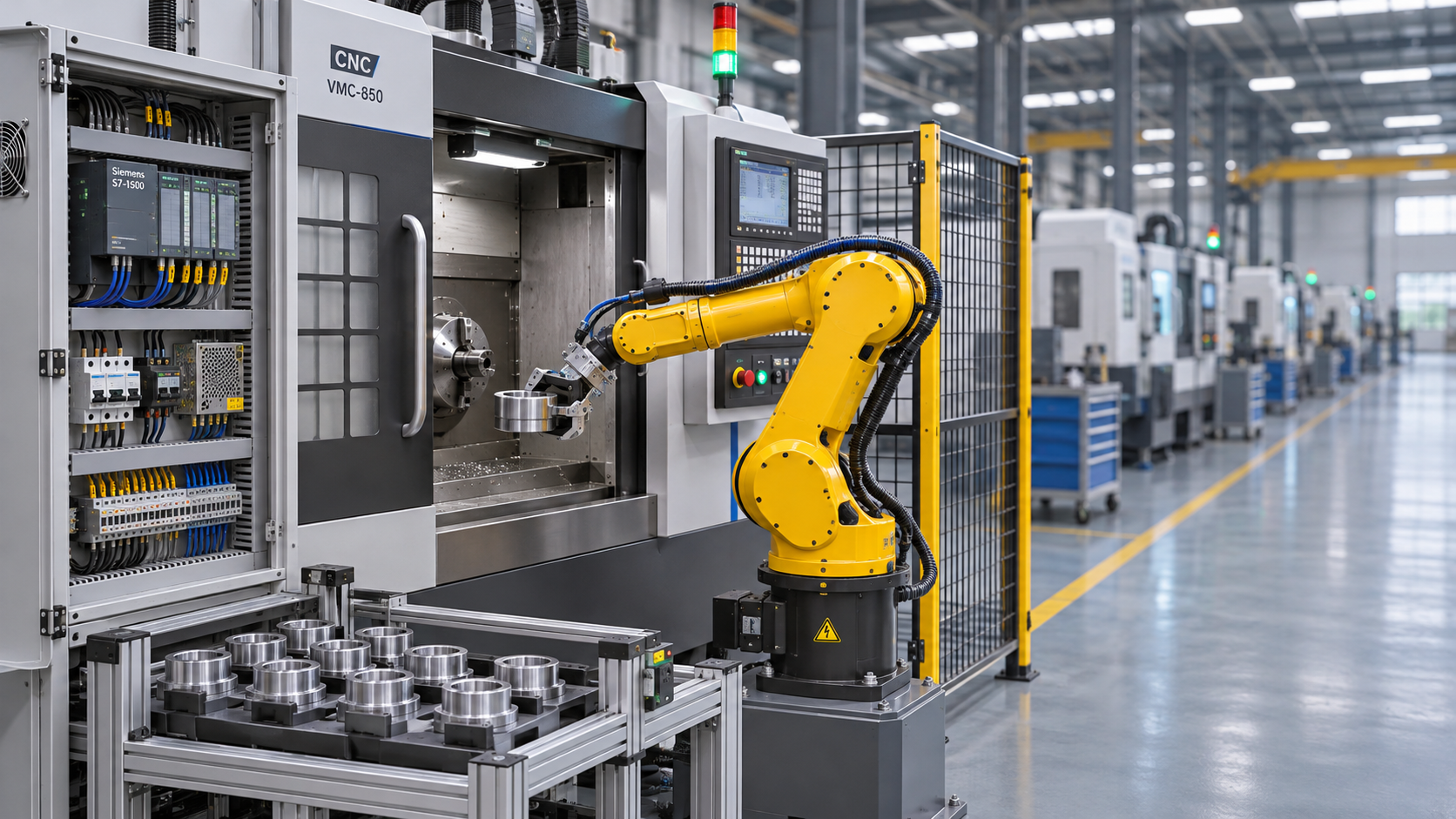
Industrial Automation integration for production line applications depends on more than connecting a PLC to a robot controller. Compatibility also involves communication protocols, safety functions, cycle-time requirements, and coordination with CNC machines and other equipment. A robot that accepts commands from a PLC may still be a poor fit if its interface cannot support the recovery sequences or production rates the cell requires.
The most useful assessment starts with the complete operating sequence, not a list of matching network logos. Define how a part enters the cell, how the robot handles it, when the CNC machine releases it, and what must happen after an interruption. Those details expose integration risks while there is still time to change the architecture.
Start with the cell sequence and control ownership
In a typical CNC tending cell, the PLC coordinates equipment states, the robot controller manages robot motion, and the CNC controller controls machining. That division is common, but it should never be assumed. Establish which controller owns each decision: opening the machine door, confirming the chuck or fixture state, starting a robot program, requesting a machining cycle, and handling a rejected part.
A sequence chart or state diagram is more useful than a general statement that the equipment is “compatible.” Show the conditions for each transition and the response if a signal does not arrive. For example, before the robot enters a lathe, the control system may need confirmation that the spindle is stopped, the door is open, the workholding device is in the required state, and the robot has permission to enter. Which confirmations are safety-related must be determined by the risk assessment.
Also agree on the source of truth. If the PLC says a part is present but the robot controller says the gripper is empty, the system needs a defined response. Simply retrying a command can turn a recoverable fault into a collision or a damaged workpiece.
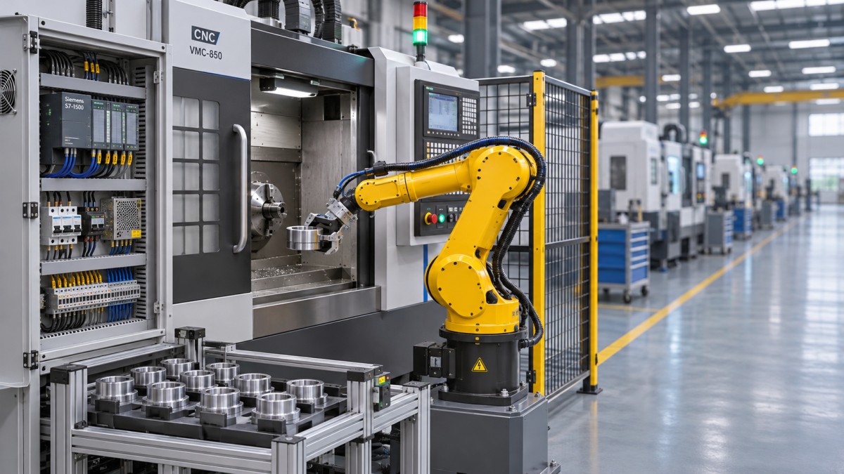
Check communication beyond the protocol name
A shared industrial Ethernet protocol is a useful starting point, not proof that two devices will work together. PLCs and robot controllers may support PROFINET, EtherNet/IP, EtherCAT, or another network, but support depends on the controller model, software version, installed hardware, and licensed options. Check the role each device can assume on the network and whether the required device-description files and configuration tools are available.
Ask for the actual interface documentation. It should identify cyclic input and output data, available diagnostics, command formats, and any limits on data size or update settings. If the robot supplier offers a standard PLC interface, verify that it exposes the functions needed for the application rather than only basic start and stop commands.
The distinction between a command and an acknowledged state matters. A PLC output requesting “open gripper” does not confirm that the gripper is open. Where the process requires it, feedback should come from a suitable sensor or a validated device status, not merely from the command bit. The same principle applies to doors, clamps, and part-present signals.
When hardwired I/O is the better choice
A small cell with a limited set of signals may not need a complex network interface. Hardwired I/O can be straightforward to troubleshoot and may suit an older CNC machine with limited connectivity. Its trade-offs are wiring effort, panel space, and less detailed diagnostics. Networked I/O is often more flexible when a cell has many states or needs richer fault information, but it introduces configuration and lifecycle dependencies.
Neither method removes the need to specify signal behavior. Define what happens on power loss, communication loss, controller restart, and conflicting inputs. If a gateway is proposed between different networks, include it in the failure analysis: it adds another device, configuration file, and support responsibility.
Treat safety compatibility as a separate design task
Standard PLC communication is not automatically safety-rated communication. A normal “robot stopped” status may be useful for sequencing, but it must not be treated as a protective function unless the complete safety design supports that use. Determine whether the cell needs hardwired safety signals, a compatible safety network, or a combination of both.
The assessment should cover the robot, CNC machine, guarding, access doors, emergency stops, and any safe-motion or monitored-stop functions used in the application. Identify the required safety functions and performance targets through a documented risk assessment; then verify that the selected components, architecture, and implementation can meet them. Relevant standards can include ISO 12100 for risk assessment, ISO 10218 for industrial robot safety, and ISO 13849 for safety-related control systems. Confirm the applicable editions and local requirements for the installation.
Be especially careful at the CNC door. A machine-ready signal can help coordinate production, but it does not by itself establish that a person or robot can safely enter the machine envelope. The machine tool builder’s interface, the robot integrator’s design, and the cell-level safety system must be reviewed together. The integrator responsible for the complete cell needs to be identified before equipment is ordered.
Test the cycle, not just the network speed
A fast network cannot compensate for a sequence that waits unnecessarily at every step. Build a cycle-time model that includes robot travel, gripper actuation, fixture confirmation, door movement, part verification, and the PLC-to-robot handshake. Include the CNC machining cycle and determine which actions can safely overlap with it.
For example, preparing the next blank while a machining center is cutting may be useful if the layout, process, and safety design permit it. By contrast, speeding up a robot movement may produce little benefit when the machine door or part-clamping sequence dominates the exchange. Multi-axis machines and complex fixtures can add access constraints that are not apparent from the quoted robot payload and reach.
Compare the required line rate with a realistic sequence, including normal variation and the handling of parts that fail a check. Network update time is only one contributor. PLC scan behavior, robot program logic, device response, and any gateway processing also affect when an action can begin. Where timing is critical, request a representative test rather than relying on nominal specifications alone.
Plan the handshake and recovery before programming
An effective handshake distinguishes at least a request, acceptance, completion, and fault. The exact signals depend on the equipment, but both sides must agree on when a command can be issued, how long it remains valid, and what clears it. A timeout should lead to a defined diagnostic state, not an unexplained reset loop.
Recovery is where many apparently compatible systems become difficult to operate. Consider a power interruption while the robot is holding a finished shaft inside a lathe. After restart, the PLC may have lost its previous sequence state, while the physical part and gripper have not moved to a known condition. The recovery procedure needs a way to establish the actual situation, protect against unexpected motion, and return control to a known state.
Review these situations with the machine operator, maintenance team, and integrator:
- A part is missing, double-loaded, or not seated in the fixture.
- The CNC cycle ends in an alarm rather than a normal completion state.
- A guard is opened during an automatic sequence.
- The robot or PLC restarts after a network interruption.
- A tool change, manual inspection, or maintenance operation changes the expected production state.
For each case, specify what is displayed, who may intervene, what must be checked, and whether automatic restart is permitted by the safety design. Avoid recovery logic that depends on an operator guessing which device is right.
Check CNC interfaces and equipment lifecycle support
The robot and PLC can be a good match while the CNC machine remains the limiting interface. Confirm the machine builder’s approved connections for cycle start, feed hold, door control, workholding, alarms, and operating modes. Some functions may require options, additional hardware, or builder involvement. On older machines, documentation and spare parts can be more consequential than the theoretical capability of the network.
For internationally sourced equipment, also check who provides technical support across suppliers and time zones, what language the electrical drawings and alarm descriptions use, and who owns changes to the interface. Version control matters: a replacement controller, firmware update, or modified robot program can affect a previously tested connection. Keep backups of PLC, robot, CNC interface, safety, and network configurations, with restoration procedures agreed in advance.
Make the decision with evidence from an acceptance test
Before committing to a PLC and robot combination, ask each supplier for the exact controller models, software versions, interface options, signal lists, and prerequisites included in its proposal. Mark any item that depends on a third party or remains unverified. A lower-cost controller is not necessarily the lower-risk choice if essential interfaces, safety options, or engineering tools are excluded.
The acceptance plan should exercise more than a successful automatic cycle. Include communication loss, rejected parts, device alarms, mode changes, power recovery, and the agreed safety-function validation. A factory acceptance test can expose interface and sequence problems before shipment; site acceptance should then confirm performance with the actual machine, tooling, parts, and installation conditions.
The practical decision is not whether two controllers can exchange a signal. It is whether the complete cell can exchange the right information, meet the required cycle, stop safely, and recover predictably—with clear responsibility when something changes.
Recommended for You
![]() Chinese Five-Axis Machine Tool Prices Reach Around 40,000 YuanMachine Tool Industry Editorial Team
 Choosing a Machine Tool Exporter: Delivery, Warranty and Support ChecksGlobal Machine Tool Trade Research Center
![]() US Lawmakers Warn China Has Overtaken US in Four Manufacturing SectorsManufacturing Policy Research Center
 What Is CNC Cutting? How It Works and Which Materials It Can CutCNC Machining Technology Center
![]() Philadelphia Fed Manufacturing Index Falls to 6.3, a Six-Month LowManufacturing Market Research Center
 Choosing a Shaft Parts Manufacturer in Japan: Quality, Capacity and Lead TimesGlobal Machine Tool Trade Research Center


Aris Katos
Future of Carbide Coatings
15+ years in precision manufacturing systems. Specialized in high-speed milling and aerospace grade alloy processing.
▶
World Intelligent Manufacturing Conference Opens in Nanjing on November 19 with 400+ ExhibitorsMachine Tool Industry Editorial Team▶
Production Line Automation Integration: How to Assess PLC and Robot CompatibilityMachine Tool Industry Editorial Team▶
Integrating Industrial Automation into Existing Production Lines: Key StepsMachine Tool Industry Editorial Team▶
Can Industrial Robots Load and Unload CNC Machines Safely? Key SafeguardsMachine Tool Industry Editorial Team▶
Automated Production Line Quotation: What Costs Should Buyers Check?Machine Tool Industry Editorial Team
▶
Mastering 5-Axis Workholding Strategies
Join our technical panel on Nov 15th to learn about reducing vibrations in thin-wall components.

Providing you with integrated sanding solutions
Before-sales and after-sales services
Comprehensive technical support