• Global CNC market projected to reach $128B by 2028 • New EU trade regulations for precision tooling components • Aerospace deman
NYSE: CNC +1.2%LME: STEEL -0.4%

How to Select a Machine Tool for Aerospace Parts with Tight Tolerances?
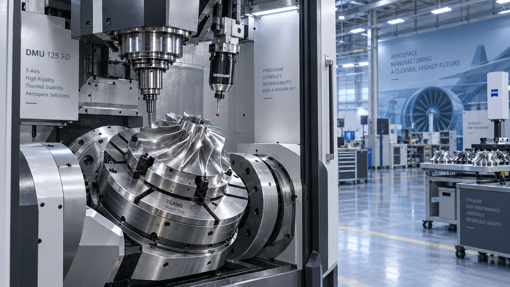
A machine tool for aerospace work should be selected around the part, the process window, and the evidence required to prove repeatability. A machine that can produce one acceptable first article is not necessarily suitable for production of flight-critical or tightly controlled components. The practical question is whether it can hold the required geometry after roughing, finishing, tool changes, thermal growth, part repositioning, and shifts in material condition.
For aerospace parts with tight tolerances, spindle speed and advertised positioning accuracy are only starting points. Structural stiffness, thermal behavior, rotary-axis performance, workholding, probing, control capability, and service support usually have a greater effect on whether the machine will remain capable in daily use.
Start with the finished part, not the machine category
Before comparing suppliers, define the part families the machine must support. Aerospace components vary widely: thin-walled aluminum structures, titanium blisks, nickel-alloy turbine features, landing gear elements, precision housings, shafts, and complex prismatic parts place very different demands on a machine.
Build the evaluation around the most demanding representative parts rather than the average part. Record the material, blank form, finished envelope, maximum mass, minimum wall thickness, critical tolerances, datum scheme, surface requirements, and expected batch pattern. Also identify whether the component requires single-setup machining, deep cavities, angled holes, complex contours, or machining on multiple faces.
This step prevents a common purchasing error: choosing a general-purpose machining center with enough travel but insufficient stiffness, rotary-axis access, or thermal control for the actual process. Axis travel tells you whether a part fits. It does not tell you whether the part can be machined accurately and consistently.
Match the machine architecture to the process risk
Three-axis machines remain appropriate for stable prismatic components that can be fixtured securely and completed with limited refixturing. They are often easier to program, inspect, and maintain. However, their apparent simplicity can create tolerance risk when a complex aerospace part requires repeated repositioning. Each new setup introduces another opportunity for datum transfer error, clamping distortion, or operator variation.
A five-axis machining center is often justified when the component has compound angles, deep cavities, impeller-like forms, or features distributed across several faces. The benefit is not simply the ability to cut more complex shapes. Reducing setups can preserve datum relationships, shorten handling time, and avoid repeated clamping of thin or distortion-prone workpieces.
That does not mean five-axis is automatically the right answer. A highly capable multi-axis machine can be an expensive and inefficient choice for a stable family of simple parts. Rotary axes add kinematic complexity, require calibration discipline, and make workholding and post-processing more demanding. The decision should be based on whether fewer setups materially reduce tolerance risk or unlock required tool access.
Separate catalog accuracy from process capability
Published positioning accuracy, repeatability, and resolution are useful comparison points, but they should not be treated as proof that the machine will hold a finished-part tolerance. A part result is influenced by the entire system: machine geometry, spindle runout, cutting forces, tool condition, fixture compliance, coolant temperature, measurement method, and program strategy.
For this reason, the evaluation should ask how the builder demonstrates performance under realistic machining conditions. Static axis measurements are relevant, but they do not replace a representative cut. A useful acceptance exercise includes a workpiece material close to production, comparable tool overhang, representative machining loads, critical features, and inspection from the intended datums.
Look beyond whether a feature is in tolerance once. The useful evidence is whether dimensions remain controlled through a sequence of parts and after ordinary interruptions such as tool replacement, warm-up, or pallet change. When tolerance bands are narrow, the repeatability of the process matters more than a favorable isolated result.
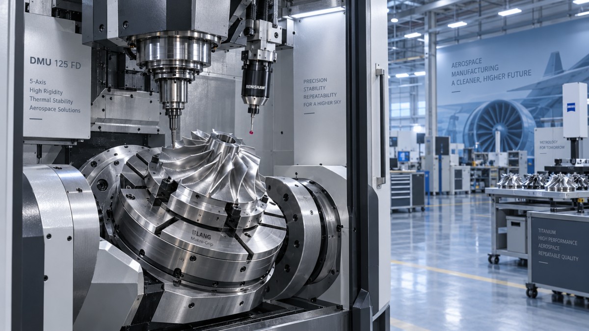
Rotary-axis behavior needs particular attention on five-axis equipment. Evaluate positioning and repeatability, but also consider axis clamping, contouring smoothness, backlash compensation behavior, and the machine’s ability to maintain geometry across the working envelope. A rotary table that performs well near one position may not produce the same result across every angle and load condition.
Thermal stability is often the hidden selection criterion
Aerospace machining can involve long cycles, heavy roughing followed by precise finishing, and materials that generate substantial heat at the cutting zone. As temperatures change, the spindle, ballscrews, cast structure, fixture, workpiece, and coolant system do not all expand at the same rate. The resulting movement may be small, but it can be large relative to critical feature tolerances.
A thermally stable machine tool for aerospace production should have a deliberate approach to heat management. That may include controlled spindle cooling, cooled drive components, consistent coolant management, temperature sensing, compensation functions, and a machine structure designed to limit distortion. The specific design is less important than understanding how the system behaves during the actual duty cycle.
Ask the supplier to explain warm-up requirements, compensation logic, expected sensitivity to shop temperature changes, and the conditions under which stated accuracy is achieved. Also assess the operating environment. Even a capable machine can struggle if it is exposed to uncontrolled drafts, large temperature swings, inconsistent coolant temperature, or poor chip management.
Thermal behavior should also shape the process plan. Finishing critical bores immediately after aggressive roughing may be less stable than allowing the part and fixture to reach a more predictable condition. Selecting the machine and developing the machining sequence are connected decisions; neither can be evaluated in isolation.
Assess spindle performance by material and cutting strategy
Maximum spindle speed is frequently overemphasized. Aluminum aerospace structures may benefit from high rotational speed and rapid, smooth axis motion, especially where small tools, thin sections, and high material-removal rates are involved. Difficult alloys often demand a different balance: torque, rigidity, damping, cooling, and dependable power delivery at the cutting speeds used by the process.
Review the usable spindle performance curve rather than only the maximum value on a brochure. The same principle applies to tool interface selection. The interface must provide adequate rigidity, repeatable tool seating, and acceptable runout for the operations being performed. Long-reach tools, deep cavities, and fine finishing operations magnify any weakness in the spindle-tool-holder assembly.
Spindle reliability is also a quality issue. For tight-tolerance work, it is important to know how the machine detects unusual vibration, overload, temperature conditions, or tool breakage. Monitoring does not eliminate process development, but it can prevent a drifting condition from becoming a batch-level quality problem.
Workholding and chip control belong in the capital-equipment decision
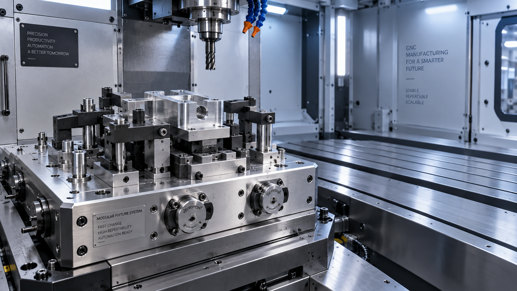
A machine cannot compensate for an unstable fixture. Aerospace parts are often difficult to clamp because the finished geometry is thin, open, or easily distorted. Fixtures must locate the part from meaningful datums while providing enough support to resist cutting force without over-constraining the component.
Evaluate the machine with the fixture concept in mind. Check table access, load capacity, available clamping area, clearance around rotary axes, hydraulic or pneumatic routing, and access for probing and tool changes. A workholding design that fits on paper can become impractical once tool reach, chip flow, and inspection access are considered.
Chip evacuation is equally important for titanium and nickel alloys, deep pockets, and long unattended cycles. Recut chips can damage surfaces, increase heat, break tools, and create inconsistent dimensions. Confirm the coolant delivery arrangement, filtration approach, conveyor design, enclosure access, and ability to clear chips from the actual orientation in which the part will be machined.
In-process measurement should close a defined control loop
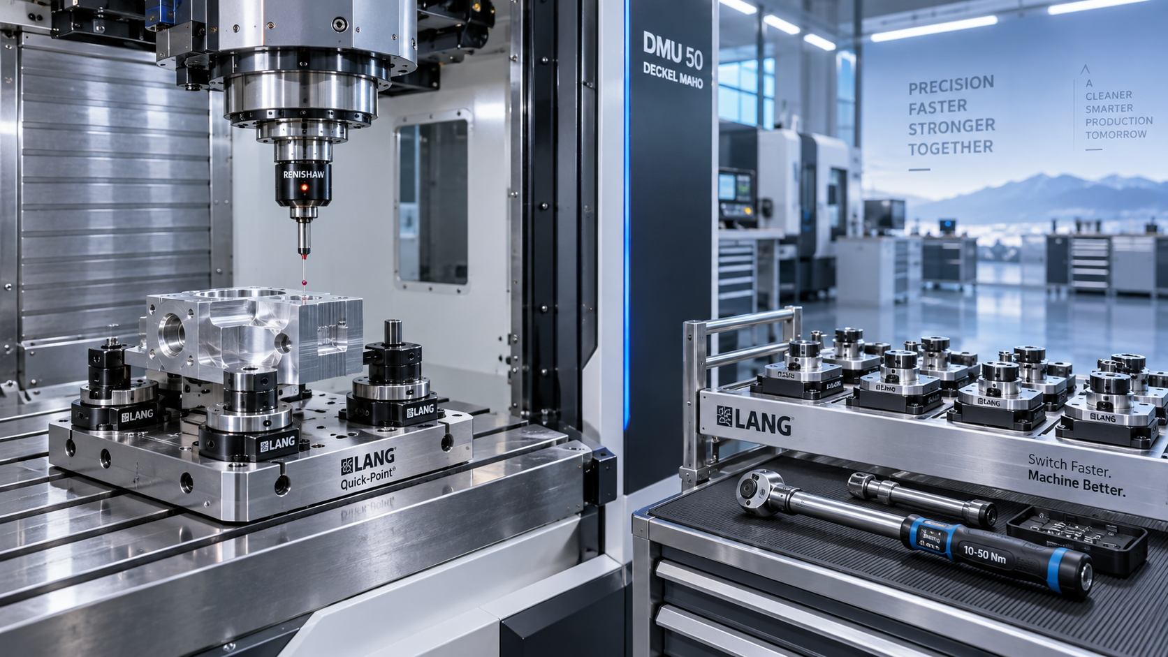
A probe is valuable only when its data changes a decision. On-machine probing can establish work offsets, confirm seating after a pallet transfer, check stock condition, locate datums, and measure selected features between operations. It can reduce handling and help contain errors before final inspection.
It should not be assumed to replace all external measurement. Some aerospace features require dedicated gauges, controlled measuring conditions, or inspection methods beyond the practical limits of a machine enclosure. The selection question is therefore not “Does the machine have probing?” but “Which measurements will be made on-machine, how will results be interpreted, and what action follows an out-of-control result?”
For production use, favor a control platform that supports clear offset management, tool-life tracking, protected programs, alarm history, and data export compatible with the facility’s quality workflow. Traceability is strongest when tool data, machining records, probing results, and inspection outcomes can be connected to a specific part or batch without relying on manual reconstruction.
Automation should stabilize the process before it increases hours
Pallet systems, robot loading, tool magazines, and unattended operation can improve throughput, but they also make weak processes fail faster. Automation is suitable when the loading datum is repeatable, workholding is robust, chip control is proven, tool life is understood, and recovery from a stoppage is defined.
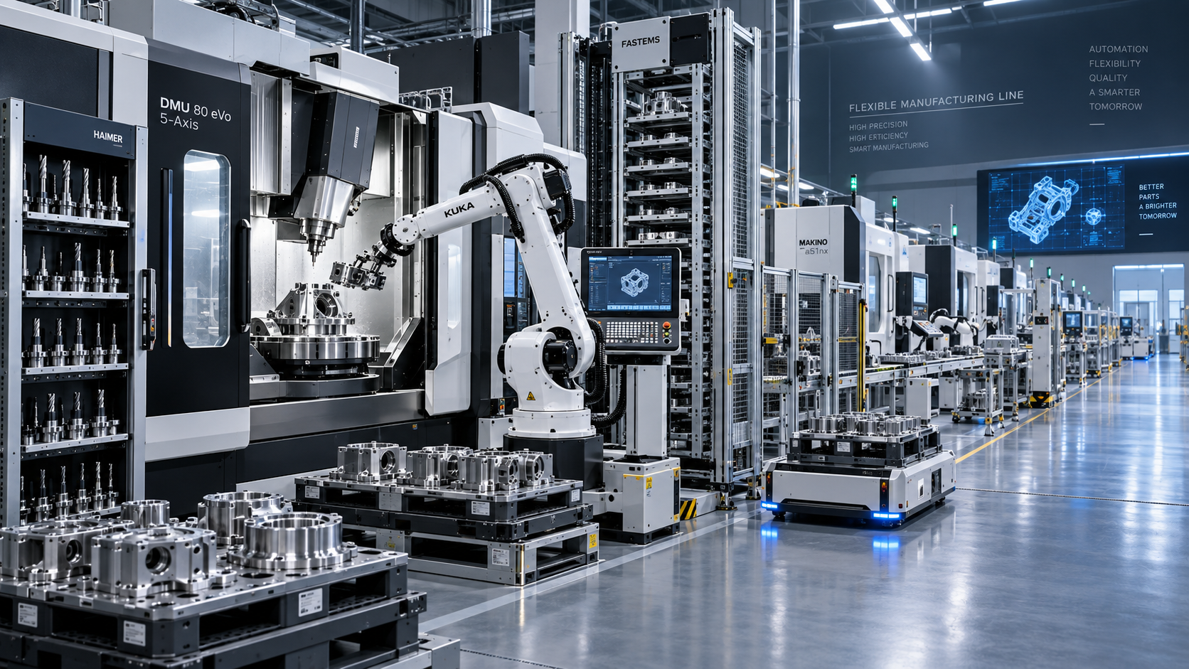
For mixed aerospace production, flexibility may be more valuable than maximum automation. A pallet pool with reliable identification and setup control may suit a variable part mix better than a dedicated robotic cell. For repeat families with longer production runs, more extensive automation can be justified once the machining process is stable.
Consider the full operating sequence: loading, part identification, clamping verification, probing, machining, tool monitoring, unloading, segregation of suspect parts, and data capture. A proposal that only demonstrates automatic loading has not yet demonstrated an unattended aerospace process.
Use the acceptance plan as the final selection filter
Before placing an order, convert the technical requirements into an acceptance plan that both sides can understand. It should define the representative part or test piece, material condition, critical characteristics, measurement method, fixture responsibility, tool strategy, cycle conditions, and permitted corrective actions. This gives the evaluation team a practical basis for comparing competing proposals.
A strong selection sequence usually follows this order:
- Rank part families by tolerance risk, geometry, material, and annual demand.
- Decide whether single-setup machining is necessary for datum control or only desirable for productivity.
- Screen machine architectures for stiffness, travel, access, spindle behavior, and workholding compatibility.
- Review thermal management, probing, control functions, chip handling, and maintenance access.
- Run or specify a representative machining and inspection trial.
- Compare lifecycle factors: application support, operator training, calibration practices, spare parts, and service response.
The lowest purchase price can become the highest-cost option if it requires excessive manual adjustment, frequent recovery after drift, repeated inspection delays, or additional setups to protect part geometry. Conversely, the most sophisticated platform is not automatically economical if its capability is rarely used.
Questions that expose weak proposals
When two machine proposals appear similar, the differences usually emerge through practical questions. How is thermal growth managed during a full production cycle? What fixture envelope remains after allowing for rotary-axis clearance? Can the supplier demonstrate the required accuracy at the intended tool reach? How are probe results used to control offsets? What happens after a tool-break or pallet-location error? How easily can operators access the work zone for inspection and recovery?
The answer should describe a complete process, not simply list installed options. A high-speed spindle, a probing package, or a pallet changer only adds value when it supports the specific tolerance-control problem present in the part family.
Selecting equipment for aerospace precision work is ultimately a decision about controllable variation. Choose the platform that gives the required access and productivity while making thermal movement, clamping behavior, tool condition, and measurement feedback easier to manage. That is the foundation for producing complex parts repeatedly, not merely achieving an impressive demonstration cut.
PREVIOUS ARTICLE
NEXT ARTICLE
Recommended for You
 How to Select a Machine Tool for Aerospace Parts with Tight Tolerances?Machine Tool Industry Editorial Team
 How to Select CNC Equipment for High-Mix, Low-Volume ProductionCNC Machining Technology Center
 Can CNC Machining Inconel Control Tool Wear in High-Temperature Aerospace Parts?CNC Machining Technology Center
 Machine Tool Market Outlook: Demand Drivers, Capacity Shifts, and Investment RisksManufacturing Market Research Center
 Zero-Point Clamping or Modular Fixtures? Choosing a Faster CNC Changeover SystemCNC Machining Technology Center
 How to Cut CNC Fixture Changeover Time Without Sacrificing Part AccuracyCNC Machining Technology Center

Aris Katos
Future of Carbide Coatings
15+ years in precision manufacturing systems. Specialized in high-speed milling and aerospace grade alloy processing.
▶
How to Select a Machine Tool for Aerospace Parts with Tight Tolerances?Machine Tool Industry Editorial Team▶
How to Compare Machine Tools for Small-Batch vs Mass Production JobsMachine Tool Industry Editorial Team▶
Multi-Axis Machine Tool Selection Guide: Travel, Spindle, Accuracy, and Control SystemMachine Tool Industry Editorial Team▶
How to Evaluate Precision Equipment for Tight-Tolerance Parts and Stable OutputMachine Tool Industry Editorial Team▶
KATS Tightens CNC Grinder Import Test RulesMachine Tool Industry Editorial Team
Mastering 5-Axis Workholding Strategies
Join our technical panel on Nov 15th to learn about reducing vibrations in thin-wall components.

Providing you with integrated sanding solutions
Before-sales and after-sales services
Comprehensive technical support