• Global CNC market projected to reach $128B by 2028 • New EU trade regulations for precision tooling components • Aerospace deman
NYSE: CNC +1.2%LME: STEEL -0.4%

CNC Lathe Quick Installation Guide: Alignment Checks Before First Production Run
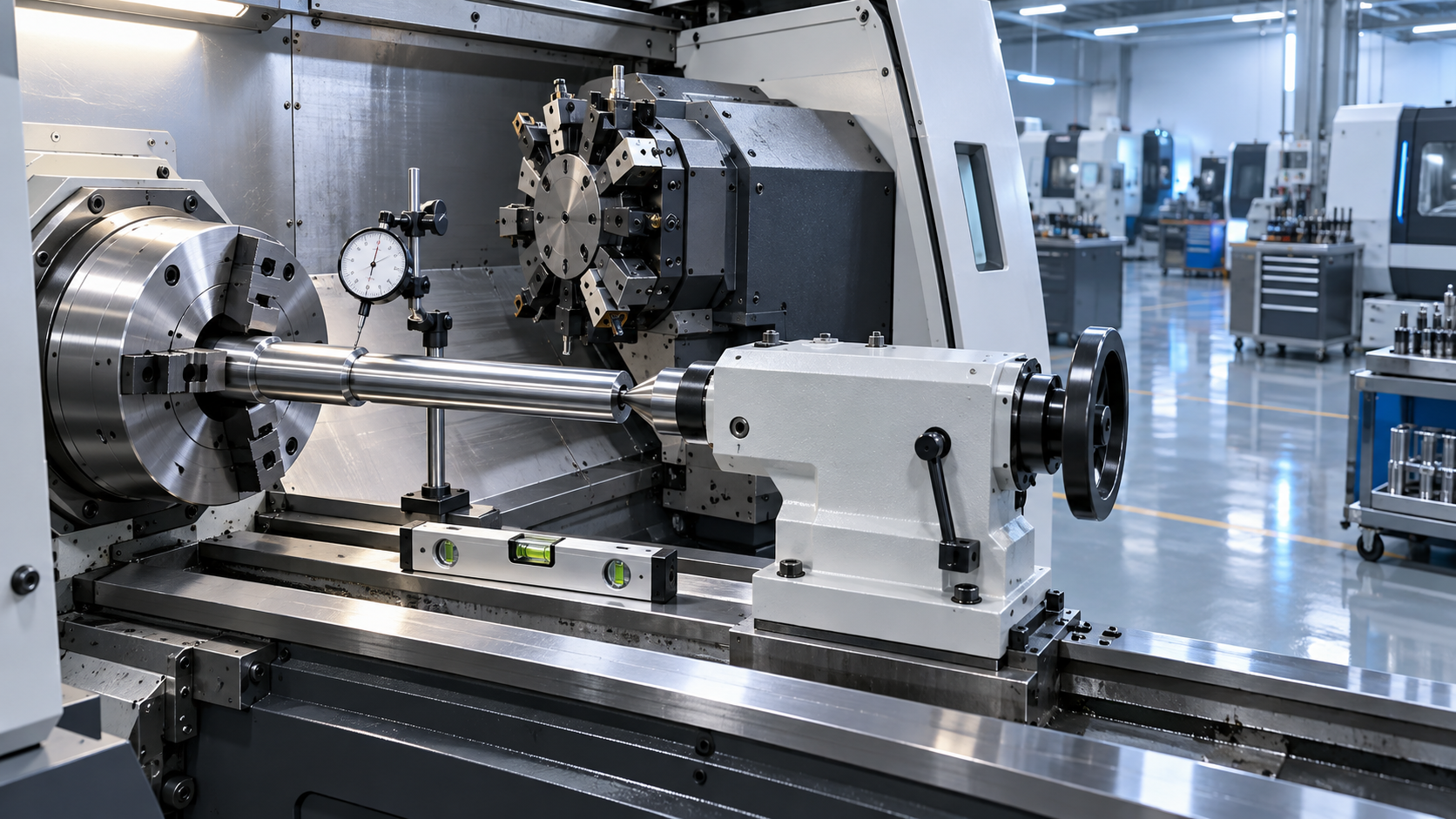
A successful first production run begins long before the first chip is cut. A CNC lathe may arrive from the factory with excellent geometric accuracy, but transport, foundation conditions, utility connections, and hurried setup work can all affect how that accuracy appears on the shop floor. For an operator, the first hours after installation are not just a commissioning task—they are the moment to establish whether the machine will produce stable parts or create a long trail of unexplained taper, chatter, tool wear, and offset corrections.
This CNC Lathe Quick Installation Guide focuses on the alignment checks that should be completed before regular production begins. It is intended for operators, setup technicians, and production teams working with CNC turning centers, horizontal lathes, and similar precision turning equipment. The exact tolerances must always follow the machine builder’s manual and the requirements of the parts being produced. Still, the inspection sequence below provides a practical framework for recognizing problems before they reach a production batch.
Do not start with a test part—start with the machine’s surroundings
When a lathe produces inconsistent results after installation, the temptation is often to adjust tool offsets, change inserts, or edit the program. Those actions may hide a symptom, but they rarely solve the underlying issue. Before checking spindle runout or tailstock alignment, make sure the machine is sitting in a condition where accurate measurement is possible.
Inspect the installation area for obvious sources of instability: an uneven or weak foundation, nearby presses or grinding machines that transmit vibration, direct sunlight across one side of the machine, or strong air drafts around the bed. Thermal change is especially easy to underestimate. A cold machine placed near an open loading door may behave differently after several hours of spindle operation, even when its initial check looked acceptable.
Confirm that the CNC lathe is firmly supported on its leveling elements or foundation pads. Remove shipping brackets and transport locks only according to the manufacturer’s instructions. Also verify that electrical supply, grounding, air pressure, hydraulic fluid, lubrication, and coolant levels meet the specified conditions. A machine that is not receiving stable air or hydraulic pressure can create clamping and turret-positioning issues that look like alignment errors.
Leveling is the reference for nearly every other check
Leveling a CNC lathe is not simply about making the machine look horizontal. The goal is to prevent bed twist. Even a rigid cast bed can distort slightly when support points are adjusted unevenly. That distortion may change the relationship between the spindle centerline, turret travel, and tailstock axis. The machine may still run, but long workpieces can show taper, boring operations may drift, and turret tools can behave differently at opposite ends of travel.
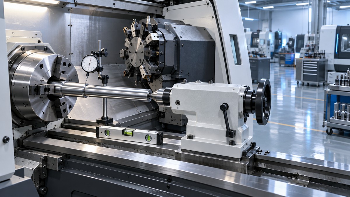
Use a calibrated precision level appropriate for machine installation. Clean the measuring surface first; a tiny chip, burr, or film of oil under the level can mislead the entire process. Measure in the directions recommended by the machine builder, commonly along the bed and across designated reference surfaces. Take readings near the headstock, through the central travel area, and toward the tailstock end rather than relying on one location.
Adjust the leveling screws gradually. Large corrections at one corner can introduce a new twist elsewhere. After each adjustment, let the machine settle briefly and repeat the readings. Once the desired level is reached, tighten locking hardware as specified and check again. It is common for readings to change slightly after bolts are secured.
A useful operating habit is to record the final level readings in the installation log. Recheck them after the first few days of operation, after moving heavy bar feeders or automation equipment into position, and whenever the machine has been relocated. This record gives maintenance personnel a valuable baseline if precision concerns appear later.
Warm the machine before judging its accuracy
A stationary machine and a production-ready machine are not always the same thing. Spindle bearings, ballscrews, hydraulic systems, and cast components respond to temperature. Before making final alignment decisions, perform the warm-up cycle recommended by the manufacturer. If no automatic cycle is provided, run the spindle through a controlled range of speeds and move the axes gently across their travel without cutting.
Do not conduct a final test cut immediately after power-up on a cold morning. Give the machine time to reach a stable operating condition, especially if it will be used for close-tolerance shaft work, long bores, or components with demanding concentricity requirements. The warm-up period is also a good opportunity to listen for unusual spindle noise, inspect lubrication delivery, and confirm that axis movement is smooth without alarms or hesitation.
Spindle checks: start at the workholding point
The spindle is the center of the turning process, yet many installation problems are not caused by the spindle itself. Chips, protective grease, handling damage, or poor seating between the spindle nose and chuck can create runout that appears to be a bearing problem. Clean the spindle nose, mating surfaces, chuck register, and mounting bolts carefully before measurement.
With the chuck or collet system installed, use a dial indicator to check radial runout at an appropriate reference point. The best point depends on the workholding design: it may be the chuck body, a test bar held in a collet, or a known straight workholding mandrel. Follow the machine builder’s allowable limits rather than applying a generic number. The purpose is to determine whether the spindle, chuck, and holding method are concentric enough for the planned work.
If runout is higher than expected, isolate the source instead of immediately adjusting components. Check the spindle nose without the chuck where permitted, then inspect the chuck seating, jaw condition, and clamping method. Soft jaws that have not been bored in place, worn hard jaws, or a test bar clamped inconsistently can all produce misleading readings.
For bar-fed work, also check the relationship between the spindle and bar feeder. A feeder that is offset or poorly supported can force the material off-center, increasing vibration and affecting surface finish. This becomes more noticeable with long stock, small diameters, or high-speed turning.
Check turret, toolholder, and center-height relationships
A perfectly leveled lathe can still cut poorly if the turret or tooling is not set up correctly. Index the turret through every station and confirm that it locks positively with no unusual noise or resistance. Inspect toolholders for clean seating surfaces and correct clamping. A small chip trapped beneath a holder can change center height or tool orientation enough to affect a fine finishing pass.
For external turning tools, verify that the cutting edge is positioned on the spindle centerline according to the tool and process requirements. A tool set too high or too low can alter cutting forces, surface finish, chip flow, and shoulder geometry. For boring bars, confirm that the bar is supported adequately and extends only as far as necessary. Excessive overhang is a frequent cause of chatter, particularly during the first production run when teams are still trying to establish safe cutting parameters.
Set each tool’s geometry and wear offsets using a consistent method. Avoid entering estimated values simply to make a first part “look close.” Reliable offsets are essential for determining whether a deviation comes from the program, the cutting tool, the material, or machine alignment. When possible, retain a documented tool setup sheet that identifies holder type, insert grade, projection length, and reference method.
Tailstock alignment matters more than many short-run jobs suggest
Operators sometimes leave tailstock verification until a long-shaft order appears. That can be costly. A misaligned tailstock may not be obvious on a short component, but it can create taper, deflection, poor surface finish, premature center wear, and inconsistent dimensions as part length increases.
Begin with a visual and functional inspection. Move the tailstock across its travel and confirm that it advances smoothly, locks securely, and does not show oil leakage or unusual resistance. Check the quill for cleanliness and proper lubrication. Then use a suitable test bar or alignment method specified by the machine manufacturer to compare the tailstock centerline with the spindle axis.
There are two issues to consider: horizontal displacement and vertical displacement. Horizontal adjustment may be available on some machines, while vertical error can indicate leveling problems, wear, foundation movement, or a condition requiring service support. Do not force an adjustment outside the machine builder’s procedure. A quick mechanical correction made without understanding the cause can disturb other machine geometry.
When turning between centers, use a practical test cut to confirm the result. Machine a test bar in controlled conditions, measure diameters near both ends, and assess whether taper is consistent. Repeat the test only after confirming workholding pressure, material straightness, tool condition, and program settings. Otherwise, the measurement may point to the wrong cause.
Run an axis travel and repeatability check before cutting metal
Before loading production material, command the X and Z axes through their normal working ranges at low speed and then at typical rapid and feed conditions. Watch for cable interference, abnormal vibration, scraping noises, guard contact, or inconsistent motion. Verify that home positions, soft limits, and work envelope settings are correct. These simple observations can prevent a damaging collision during the first automatic cycle.
Check turret indexing repeatedly, including stations that may not be used on the first job. A machine may appear healthy until one rarely used station fails to clamp correctly. If the lathe includes a sub-spindle, live tools, Y-axis, parts catcher, steady rest, bar feeder, or robotic loading interface, verify each device independently before combining them in an automated sequence.
For higher-precision applications, a qualified technician may use laser measurement, ballbar testing, or other calibration equipment to evaluate positioning accuracy and backlash. Operators do not need to perform every advanced diagnostic themselves, but they should recognize when basic checks suggest that a formal geometric inspection is necessary.
The first test cut should answer specific questions
A test part is not merely a ceremonial first piece. It should be designed or selected to reveal the issues most likely to affect the production job. A simple stepped test bar can help evaluate diameter control, taper, shoulder squareness, surface finish, and repeatability. Include features that reflect the actual process: an OD turning pass, a facing pass, a bore if internal work is planned, and a center-supported section if the job uses the tailstock.
Measure the part at more than one location. Compare the first piece with a repeat cut rather than relying on a single result. If the dimensions shift after several cycles, investigate thermal stabilization, tool seating, clamping consistency, coolant delivery, or axis behavior. If taper appears, review bed level, tailstock condition, spindle-to-workholding concentricity, workpiece deflection, and cutting force before changing the program.
Surface finish also carries useful information. Regular waviness may point to vibration, insert damage, or workholding instability. A rough finish that changes along the part may indicate variable material support, tool overhang, or changing cutting load. The goal is not to diagnose every mark by guesswork; it is to build a disciplined chain from observation to verification.
Common shortcuts that create avoidable problems
- Using a carpenter’s level: General construction levels are not suitable for precision machine alignment. Use a calibrated machine level or the approved measurement method.
- Checking only once: Level readings can change after locking bolts, warming up the machine, or loading auxiliary equipment.
- Measuring on dirty surfaces: Chips and burrs under a level, indicator base, chuck, or toolholder can invalidate the result.
- Correcting offsets to hide taper: Offset changes may help one feature but leave the underlying machine or setup issue unresolved.
- Skipping the actual workholding check: A spindle can be within specification while a chuck, collet, jaw set, or bar feeder introduces unacceptable error.
- Ignoring documentation: Without baseline readings and test-part results, later troubleshooting becomes guesswork.
Release the lathe to production with a clear handover
Before regular production begins, document the final setup condition: leveling results, spindle and workholding checks, tailstock findings, tool setup data, warm-up method, test-cut measurements, and any remaining restrictions. This does not need to become burdensome paperwork. A concise installation and first-run record gives the next operator confidence that the machine was checked methodically.
A CNC lathe is expected to deliver repeatable precision in demanding environments, from automotive shafts and energy components to electronics fixtures and aerospace-related parts. That performance depends on more than the control system or the cutting program. Careful installation alignment creates the stable reference that allows every later decision—tool selection, fixture design, cycle optimization, automation integration, and inspection planning—to work as intended.
Use this CNC Lathe Quick Installation Guide as a practical starting point, then follow the specific procedures and tolerances supplied by the machine manufacturer. A few patient checks before the first production run can save far more time than a day spent correcting parts after the line is already moving.
NEXT ARTICLE
Recommended for You
 CNC Lathe Quick Installation Guide: Alignment Checks Before First Production RunCNC Machining Technology Center
 How to Select a CNC Lathe for Small Parts Without Sacrificing Accuracy or Cycle TimeCNC Machining Technology Center
 How to Select a Slant Bed Lathe for High-Precision Shaft and Chuck WorkCNC Machining Technology Center
 Smart Manufacturing for Small Businesses: Where Automation Delivers the Fastest ROIMachine Tool Industry Editorial Team
 How to Specify a CNC Lathe for High-Volume Automotive Shaft ProductionCNC Machining Technology Center
 How Automated Precision Machining Maintains Tolerance in High-Mix ProductionCNC Machining Technology Center






Aris Katos
Future of Carbide Coatings
15+ years in precision manufacturing systems. Specialized in high-speed milling and aerospace grade alloy processing.
▶
CNC Lathe Quick Installation Guide: Alignment Checks Before First Production RunCNC Machining Technology Center▶
How to Select a CNC Lathe for Small Parts Without Sacrificing Accuracy or Cycle TimeCNC Machining Technology Center▶
How to Select a Slant Bed Lathe for High-Precision Shaft and Chuck WorkCNC Machining Technology Center▶
How to Specify a CNC Lathe for High-Volume Automotive Shaft ProductionCNC Machining Technology Center▶
CNC Turning Explained: How It Works, Key Tolerances, and Best-Fit Part TypesCNC Machining Technology Center
Mastering 5-Axis Workholding Strategies
Join our technical panel on Nov 15th to learn about reducing vibrations in thin-wall components.

Providing you with integrated sanding solutions
Before-sales and after-sales services
Comprehensive technical support