• Global CNC market projected to reach $128B by 2028 • New EU trade regulations for precision tooling components • Aerospace deman
NYSE: CNC +1.2%LME: STEEL -0.4%

How Do You Evaluate a CNC Lathe's Repeat Positioning Accuracy?
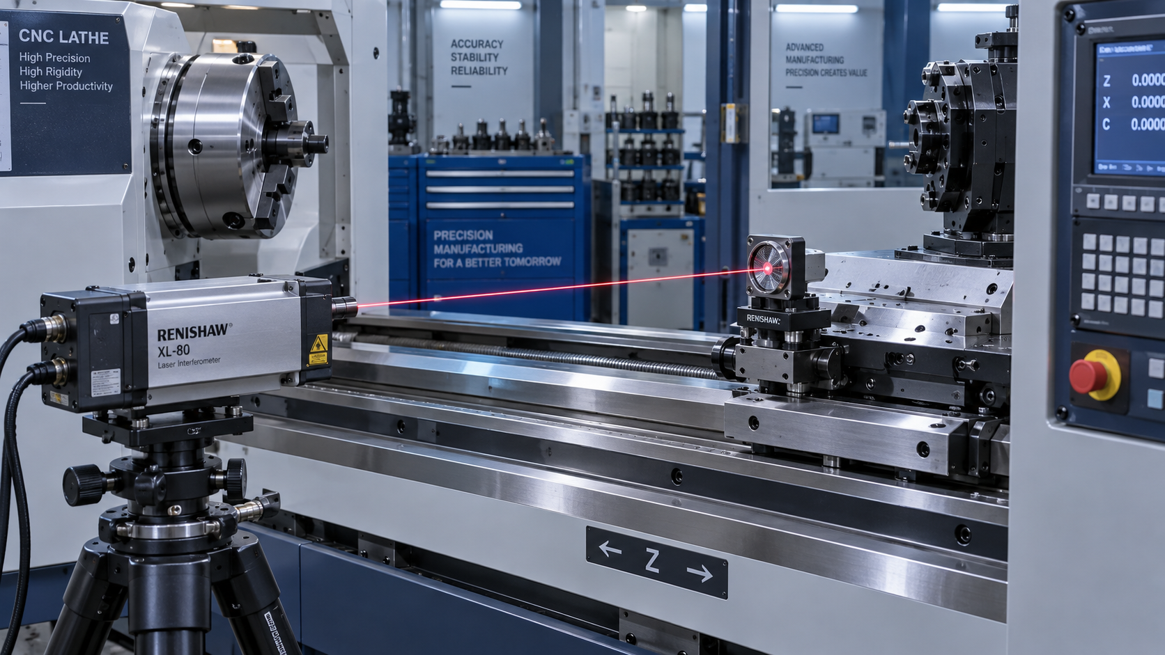
Evaluate a CNC lathe’s repeat positioning accuracy by measuring how consistently each axis returns to several commanded positions over repeated cycles, with approaches from both directions. Use an independent measuring system, control the machine’s thermal condition, and calculate repeatability using a clearly identified method. A single indicator reading or a specification labeled “±0.003 mm” is not enough to establish capability.
The essential distinction is between returning consistently and reaching the correct location. An axis can repeatedly stop at almost the same point while remaining offset from its commanded position. Reliable evaluation therefore separates positioning error, same-direction repeatability, and the effect of reversing direction.
What does repeat positioning accuracy actually measure?
Although “repeat positioning accuracy” appears frequently in machine specifications, positioning repeatability is the more precise term. It describes the dispersion of actual positions obtained when an axis repeatedly moves to the same commanded target under defined conditions.
Three measurements answer different questions:
For an illustrative example, suppose repeated arrivals at a target all fall between +7 µm and +9 µm relative to the commanded position. The observed spread is only 2 µm, but the mean positioning error is approximately +8 µm. These are hypothetical values, not machine performance benchmarks.
A position-dependent compensation adjustment may reduce a consistent error. It cannot reliably eliminate random scatter, mechanical instability, or temperature-dependent movement that changes during operation.
Which measuring equipment should you use?
A calibrated laser interferometer is suitable for evaluating linear-axis positioning across the working travel. It provides an independent displacement reference and supports repeated measurements at multiple targets. Environmental compensation, optical alignment, and stable mounting are necessary for trustworthy results.
A high-resolution electronic indicator or displacement probe can support a local repeatability check. The probe contacts a suitable reference surface, and the axis repeatedly withdraws and returns. This can help investigate a particular working position, but it does not establish performance across the whole axis.
Instrument resolution alone is not measurement uncertainty. A display that resolves 0.1 µm does not prove that the complete setup can measure repeatability to 0.1 µm. Calibration, mounting stiffness, contact behavior, thermal effects, and alignment all contribute to uncertainty.
The machine’s own position display is not an independent verification. It reports the control system’s interpretation of position. With motor-side feedback, for example, some mechanical errors between the motor and the slide may not be directly observed by the encoder.
A ballbar test can reveal contouring and reversal-related problems, but it is not a substitute for direct linear positioning measurements. Likewise, a machined test part evaluates a combination of machine, tool, workholding, material, and thermal effects rather than axis repeatability alone.
How should the machine and measurement setup be prepared?
Begin with the installation condition: leveling, foundation support, lubrication, and any mechanical faults must be addressed before interpreting micrometer-level results. Loose measurement fixtures can produce apparent axis variation that belongs to the setup rather than the machine.
Run the specified warm-up routine and document it. A machine tested immediately after startup is not directly comparable with one tested after extended axis and spindle operation. If the intended application includes long production runs, evaluate the relevant operating temperature rather than relying only on a short, stabilized laboratory-style test.
Record ambient temperature and its change during the test. For laser measurements, apply the required air-condition compensation and document material-temperature compensation where used. Avoid direct sunlight, drafts, and changing heat sources near the machine or measurement path.
Align the measurement direction with the axis under test. Angular misalignment introduces cosine error, while an offset between the measurement line and the functional point can allow angular motion to appear as linear error. The measurement location should therefore be documented, not treated as incidental.
Record the control configuration as well. Position compensation, backlash compensation, thermal compensation, feed rate, and settling time can affect the result. Testing with normal production compensation enabled is legitimate, but undisclosed changes make comparisons unreliable.
What motion sequence produces a meaningful result?
A useful evaluation samples multiple positions along each relevant axis rather than repeatedly checking one convenient location. Include the production working zone and distribute additional targets over the travel being claimed. A short local test cannot justify a full-travel specification.
For a practical diagnostic check, the sequence is:
- Select target positions and establish a repeatable travel speed and dwell time.
- Approach each target from the positive direction, stop, allow the defined settling period, and record the independent position reading.
- Repeat the arrivals enough times to characterize the variation.
- Repeat the sequence with approaches from the negative direction.
- Evaluate X and Z separately, adding other controlled axes when their performance is relevant.
Five arrivals per direction at each target can provide a useful initial diagnostic dataset, but this does not by itself establish compliance with a standard. A formal acceptance test must follow the selected standard’s requirements for target distribution, cycles, sequence, and calculations.
Provide adequate travel beyond the targets for genuine opposite-direction approaches. Keep the motion sequence consistent: changes in travel distance, acceleration, or dwell can alter heating and settling behavior.
Measure stationary positioning after the agreed settling interval. If a short production dwell is important, test that condition explicitly. A machine that settles closely after several seconds may behave differently when cutting begins almost immediately.
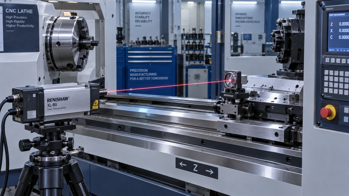
Retain the readings in acquisition order. Time-ordered data distinguish random scatter from a progressive shift as the machine warms. Combining both into a single number can conceal the underlying problem.
How should repeatability be calculated and reported?
At each target, separate the positive-approach and negative-approach readings. Calculate the mean position error and the dispersion for each direction. Then assess the separation between the directional means and apply the agreed method for bidirectional results.
For a basic shop-floor check, the maximum reading minus the minimum reading gives the observed range. This is easy to understand, but it depends on the sample count and is not automatically equivalent to a standardized repeatability value.
ISO 230-2, which addresses positioning accuracy and repeatability of numerically controlled axes, uses statistical evaluation. Its unidirectional positioning repeatability calculation uses four times the estimated standard deviation at a target. Bidirectional evaluation also accounts for the relationship between the directional distributions. A simple peak-to-peak range should not be relabeled as an ISO result.
Consider a hypothetical target where one approach direction averages +1 µm and the opposite direction averages +5 µm, with tight scatter in both groups. Same-direction repeatability may look good, yet the 4 µm directional separation indicates reversal-related behavior. Reporting only the better directional group would conceal a relevant limitation.
A useful report retains:
- Results by target, axis, and approach direction, including mean errors and dispersion.
- The overall values calculated under the named method.
- Raw readings, test sequence, travel coverage, speed, and dwell.
- Thermal conditions, compensation settings, instrument calibration, and measurement uncertainty.
Do not average away an unfavorable location. An overall mean can look acceptable while a target inside the production working zone fails the agreed limit.
Which standards and specification details matter?
ISO 230-2 provides the central framework for measuring positioning accuracy and repeatability of numerically controlled axes. ISO 13041-4 addresses positioning accuracy and repeatability tests for linear and rotary axes of numerically controlled turning machines and turning centers. The applicable edition and contractual test requirements should be identified before acceptance testing.
A specification such as “repeatability: ±3 µm” remains ambiguous without its calculation basis. It might describe a half-range, a manufacturer-defined limit, or a differently calculated statistic. These values cannot be compared safely from their labels alone.
Clarify whether the figure is unidirectional or bidirectional, which axis and travel it covers, and whether it represents guaranteed acceptance performance or an indicative result. Establish the measurement uncertainty and the decision rule for results near the limit. A reading just inside a limit does not provide strong evidence of conformity when uncertainty is substantial relative to the available margin.
For cross-machine comparisons, the test conditions must be comparable. Identical numerical specifications can represent different performance claims if one covers the entire travel in both directions and another covers only a local same-direction test.
Why does the X-axis radius-versus-diameter convention matter?
A lathe’s X axis requires special attention because the control may display or program diameter values while the slide physically moves radially. An interferometer measures actual linear displacement; its reading must be interpreted consistently with the controller’s coordinate convention.
For conventional external turning geometry, a 1 µm change in radial tool position corresponds to approximately a 2 µm change in workpiece diameter, before other cutting effects are considered. Consequently, a repeatability statement in radial displacement is not interchangeable with the same numerical value expressed on diameter.
The report should state whether X-axis values represent physical slide displacement, radius, or diameter-equivalent values. Otherwise, a factor-of-two misunderstanding can invalidate both a machine comparison and a tolerance assessment.
How can the results identify problems—and establish suitability?
Different patterns suggest different investigations, but no single pattern proves a root cause. Tight same-direction groups separated by approach direction warrant examination of reversal behavior, mechanical lost motion, friction, and compensation. Increasing scatter in one travel region warrants checks of local mechanics, lubrication, feedback, and the measurement setup.
A gradual shift with elapsed time points toward thermal behavior or movement of the measurement reference. Consistent positional errors with little scatter suggest a systematic component that may be correctable after the cause is confirmed. Irregular scatter calls for investigation before adjusting compensation; correcting a mean error will not stabilize unpredictable movement.
There is no universal repeatability value that makes a lathe suitable for every tolerance. The allowable axis contribution must fit within an error budget that also includes tool wear, spindle behavior, workholding, cutting forces, thermal drift, and inspection uncertainty.
Linear-axis testing is generally performed without cutting load. It establishes an important machine characteristic, not a guarantee of finished-part dimensions. Where the requirement concerns repeated tool changes, turret indexing repeatability must also be considered separately.
The strongest acceptance evidence combines a documented axis test with representative machining under agreed production conditions. The axis test establishes motion consistency; the cutting trial establishes whether the complete process can maintain the required features. Neither should be used to claim what only the other can demonstrate.
Recommended for You
![]() Li Daokui: China Overtakes Germany With 21.6% of Global Machine Tool ExportsGlobal Machine Tool Trade Research Center
 Machine Tool Prices: What to Budget Beyond the Purchase PriceGlobal Machine Tool Trade Research Center
![]() Survey: 81% Expect US Cutting Tool Shipments to Rise or Hold Steady in 2026Machine Tool Industry Editorial Team
 CNC Fixture Design: Locating and Clamping for Accurate MachiningCNC Machining Technology Center
![]() US Decides Against New Tariffs on Robots, Industrial Machinery and PartsManufacturing Policy Research Center
![]() White House Section 232 Ruling: No New Machine Tool or Robot Tariffs, Calls for TalksManufacturing Policy Research Center


Aris Katos
Future of Carbide Coatings
15+ years in precision manufacturing systems. Specialized in high-speed milling and aerospace grade alloy processing.
▶
Manual vs. CNC Lathe for Simple Parts: How Batch Size Affects the ChoiceCNC Machining Technology Center▶
How Do You Evaluate a CNC Lathe's Repeat Positioning Accuracy?CNC Machining Technology Center▶
How to Select a CNC Metal Lathe for Tight-Tolerance Shaft and Sleeve PartsCNC Machining Technology Center▶
CNC Lathe Quick Installation Guide: Alignment Checks Before First Production RunCNC Machining Technology Center▶
How to Select a CNC Lathe for Small Parts Without Sacrificing Accuracy or Cycle TimeCNC Machining Technology Center
▶
Mastering 5-Axis Workholding Strategies
Join our technical panel on Nov 15th to learn about reducing vibrations in thin-wall components.

Providing you with integrated sanding solutions
Before-sales and after-sales services
Comprehensive technical support