• Global CNC market projected to reach $128B by 2028 • New EU trade regulations for precision tooling components • Aerospace deman
NYSE: CNC +1.2%LME: STEEL -0.4%

How to Select a CNC Metal Lathe for Tight-Tolerance Shaft and Sleeve Parts
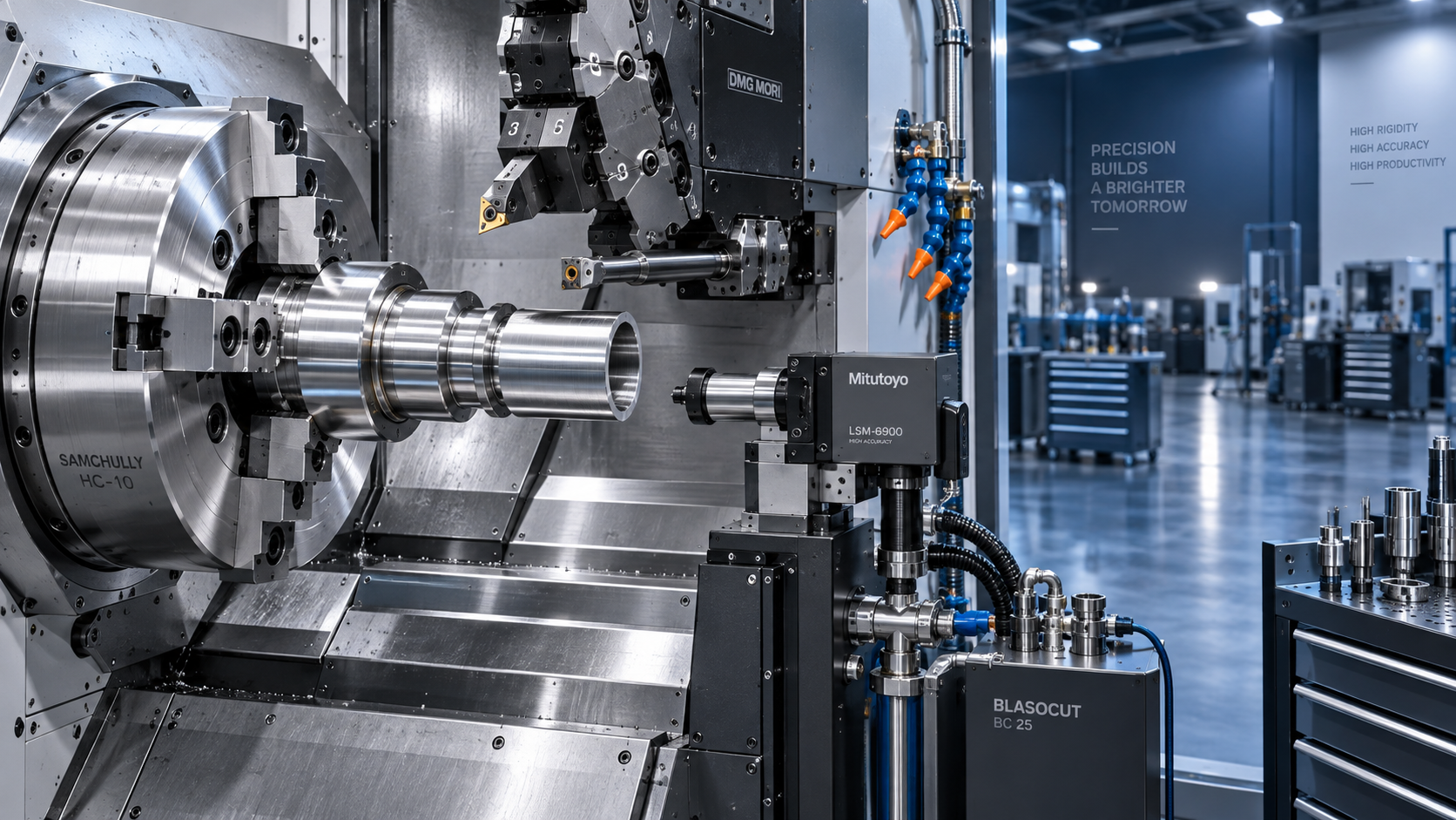
Start with the finished part, not the machine catalog. A tight-tolerance shaft or sleeve often combines diameter control, cylindricity, concentricity, shoulder location, surface finish, and bore geometry on surfaces that must remain related after the part is removed from the chuck. The selected CNC metal lathe must hold those relationships through roughing, finishing, tool changes, thermal growth, and the expected production cycle.
A machine with a fast spindle and generous bar capacity can still be a poor fit when its structure, workholding arrangement, or measurement strategy allows the part to move between operations. The useful selection question is: which machine configuration can produce the required features repeatedly from the intended material, blank form, and batch pattern?
Begin with the tolerance chain of the part
Separate the drawing requirements into features controlled directly in one setup and features that depend on a second setup or another machine. For a stepped shaft, a critical bearing journal and a locating shoulder may be turned in one clamping. For a sleeve, the outside diameter, bore, face, and internal groove may need to be coaxial within a limited runout value. That distinction determines whether a conventional two-axis lathe is sufficient or whether a sub-spindle, live tooling, or a secondary operation is needed.
Diameter tolerance alone does not describe the real machining difficulty. A narrow diameter tolerance on a short, stiff journal is normally easier to stabilize than a looser tolerance on a thin-walled sleeve with a long unsupported bore. Likewise, a shaft may measure correctly at several points yet fail because taper, lobing, or chatter marks affect fit and rotation.
Build a feature map before comparing machines. Include the maximum and minimum stock diameter, finished length, length-to-diameter ratio, bore depth, interrupted cuts, threads, grooves, cross holes, keyways, and the datum relationships that must survive transfer. This map exposes requirements that are often hidden by a simplified part envelope.
- A long slender shaft requires support planning, such as tailstock, programmable steady rest, follower rest, or a process sequence that leaves support material until late in the cycle.
- Thin-wall sleeves call for low-distortion clamping, controlled jaw contact, and a finishing strategy that accounts for elastic recovery after unclamping.
- Parts made from bar stock introduce bar straightness, residual stress, and cut-off behavior; forged or saw-cut blanks add interrupted turning and greater stock variation.
- Critical radial or axial features after transfer need a defined relationship between the main spindle and sub-spindle, rather than an assumed handoff accuracy.
Read accuracy specifications in context
Positioning accuracy, repeatability, spindle runout, and axis resolution are related but not interchangeable. Axis resolution only states the smallest commanded increment; it does not prove that the slide reaches and holds that location under cutting load. Similarly, a favorable positioning figure measured under specified test conditions does not automatically represent a finished diameter during production.
For tight shaft and sleeve work, repeatability under a stable thermal condition is often more useful than an isolated positioning statement. Finishing compensation can correct a predictable offset, but it cannot reliably correct random changes caused by stick-slip, loose mechanical interfaces, inconsistent clamping, or changing tool load. Ask how accuracy is verified, at what machine temperature, over what travel, and whether the stated values apply to a newly installed machine or an acceptance condition after a defined warm-up period.
The spindle system deserves the same scrutiny. Radial runout at the spindle nose matters, yet it is only the beginning. Chuck accuracy, jaw wear, collet condition, drawtube force, workpiece seating, and the concentricity of any soft jaws all influence the actual part axis. A lathe selected for precision collet work may perform differently when fitted with a large power chuck for rough forgings.
Rigidity is a system property
Machine mass alone is an incomplete proxy for stiffness. The relevant structure includes the bed, guideway arrangement, carriage, turret, toolholder, spindle bearings, chuck or collet, and the workpiece support. A heavy machine can still deliver unstable results if a long boring bar projects too far, a tool block has insufficient support, or the part is held on an unsuitable gripping length.
Consider the most demanding cut rather than the nominal part size. A short hardened steel journal may mainly test spindle torque and insert selection. A deep internal groove in a sleeve tests boring-bar stiffness, chip evacuation, coolant access, and vibration damping. A thin stainless sleeve can deflect because of clamping pressure even when cutting forces are modest.
Guideway design affects how the machine reacts to alternating load and frequent rapid movement. Box guideways often suit heavy interrupted work and high cutting forces, while linear guideways can provide rapid axis response and efficient movement. Neither arrangement is automatically superior for precision turning. The correct choice depends on the cutting duty, the machine builder's structural execution, and whether high acceleration is needed for the part mix. A precision finishing application benefits from smooth reversal behavior and stable support at the actual turret position used for finishing.
Thermal stability determines whether a good first part remains good
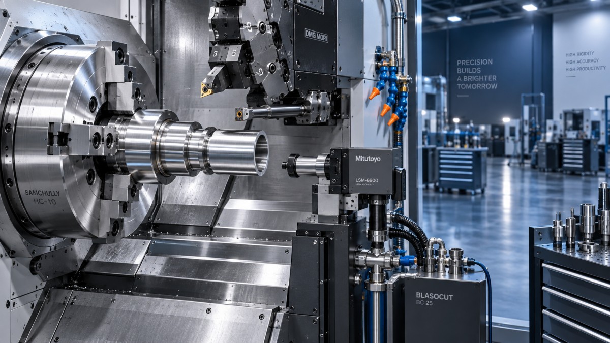
Many selection errors arise because a sample part is inspected immediately after a short test cut. During a production shift, spindle bearings warm, hydraulic systems add heat, coolant temperature changes, and repeated axis motion creates a different machine state. On a shaft, thermal movement can appear as a gradual diameter trend. On a sleeve, it can show up as a changing relationship between the bore and outside diameter.
Look for a practical warm-up and verification routine rather than relying only on compensation features. A controlled evaluation should run representative roughing and finishing cycles long enough for spindle and axis temperatures to stabilize. Measure parts throughout the run, including dimensions at separate axial locations, bore size, taper, and key datum relationships. The pattern matters: a steady trend may be manageable through controlled offsets; irregular variation points toward a problem in tooling, clamping, material consistency, or machine behavior.
Coolant deserves attention because it affects both size control and surface condition. Uncontrolled coolant temperature can shift a close diameter process, while inadequate filtration can damage seals, affect hydraulic components, and introduce fine scratches during finishing. For sleeve bores, coolant delivery must clear chips from the cutting zone. Chips packed ahead of a boring bar can mark the bore, push the tool, and create a misleading impression that the spindle lacks accuracy.
Match spindle power and torque to the actual cutting window
Maximum spindle speed is useful only when it is available with adequate power, torque, and stability at the diameter and material being machined. Small-diameter finishing may benefit from higher speed. Large-diameter roughing, threading, drilling, and grooving often occur at lower speed, where torque behavior becomes more important. Review the spindle power-torque curve instead of comparing a single peak figure.
For sleeves, internal machining may set the cycle time and quality limit even when the outside diameter is straightforward. Confirm the available bore diameter through the spindle, the clearance around the boring bar, toolholder geometry, and the machine's ability to deliver coolant to a deep bore. For shafts with milled flats, drilled lubrication holes, or timing features, determine whether live tooling and a C-axis eliminate an accuracy-risking transfer or merely add complexity that the production volume does not justify.
A sub-spindle is valuable when back-face features, second-end diameters, or concentricity requirements would otherwise require manual rechucking. Its benefit depends on transfer control. The two spindles must grip the part without bending it, and the handoff must be repeatable across the material and diameter range. Very thin sleeves may require specially designed expanding mandrels or soft contact surfaces; transferring them with excessive grip force can alter the finished bore or create out-of-roundness.
Workholding should be evaluated with the part, not as an accessory
Workholding is often the limiting element in a tight-tolerance turning process. Three-jaw chucks are flexible, but jaw force and contact pattern can distort thin sections. Soft jaws machined in place improve concentricity, yet their accuracy depends on the intended clamping diameter, jaw stroke, and the way the jaws are bored. A jaw set bored for one diameter can lose effective contact when used far outside that range.
Collets commonly offer more uniform gripping for small shafts and sleeves, particularly where runout and surface protection matter. They also impose a narrower diameter window and require appropriate stock preparation. A part with variable bar diameter or scale may seat inconsistently. For delicate sleeves, expanding mandrels can preserve the outside surface and establish a bore-based datum, but bore variation, mandrel wear, and debris on the locating surface must be controlled.
When reviewing a proposed setup, inspect where axial location is established. A part that bottoms against a contaminated chuck face may shift axially without showing an obvious radial error. Face cleanliness, stop design, and chip evacuation around the locating surface directly affect shoulder positions and overall length.
Tooling capacity must support correction without disrupting the process
A turret with enough stations is not necessarily enough. The tool layout needs room for roughing, finishing, facing, grooving, threading, drilling, boring, cut-off, and any probing or live-tool operations without forcing compromised overhangs. Finishing tools should not be positioned where adjacent holders interfere with access to a shoulder or bore.
Choose tooling interfaces that are repeatable and locally supported. Quick-change systems reduce setup time only when their seating surfaces remain clean and robust under repeated use. Long adapters and improvised shims add flexibility at the expense of rigidity. Boring bar selection is especially important: bar diameter, unsupported length, damping design, insert geometry, and coolant path should be considered together.
Tool monitoring and in-process probing can improve control, but neither replaces a stable cutting process. Probe access must be physically possible without collision, and the measurement routine must be protected from coolant, chips, burrs, and hot-part effects. A probe that measures a warm shaft immediately after a heavy roughing cut may produce an offset that becomes incorrect after the part reaches inspection temperature.
Automation changes the selection criteria
Bar feeders, gantry loaders, robots, parts catchers, and automatic gauging can reduce handling variation, but they also create new interfaces to validate. A bar feeder must match bar diameter tolerance, straightness, remnant handling, and spindle liner requirements. A robotic gripper needs enough compliance or precise location control to avoid damaging finished journals. Long shafts require support during unloading so they do not bend or strike machine surfaces.
For unattended or lightly attended production, chip management becomes a quality requirement rather than a housekeeping issue. Stringy material can wrap around parts, interfere with transfer, damage finished surfaces, or prevent proper seating at a subsequent station. Confirm the conveyor, coolant flow, chip-breaking strategy, and access for clearing a jam. A machine that produces an acceptable part under supervised test conditions may not sustain the same result when chips accumulate over a long cycle sequence.
Use a representative acceptance trial
A meaningful evaluation uses the intended material condition, realistic stock allowance, production workholding, and the planned tooling concept. Run enough parts to observe thermal behavior, tool wear progression, chip control, and transfer consistency. Inspect more than the easiest diameter. Include critical journals, bore size at multiple depths, taper, roundness where relevant, face-to-datum location, and concentricity after all operations are complete.
Record every offset change made during the trial. Frequent corrections can be acceptable during initial process development, but unexplained correction activity is evidence that the system has not yet reached stable control. Separate changes caused by predictable tool wear from those caused by clamp variation, material movement, thermal drift, or measurement inconsistency.
The best CNC metal lathe selection is the one that keeps the required geometry stable with a workable process margin. That margin comes from a compatible combination of structure, spindle behavior, workholding, tooling access, thermal management, and verification discipline. A specification sheet starts the comparison; representative cutting and inspection reveal whether the machine can hold the part.
NEXT ARTICLE
Recommended for You
 How to Select a CNC Metal Lathe for Tight-Tolerance Shaft and Sleeve PartsCNC Machining Technology Center
 How to Select an Industrial Lathe for High-Volume Shaft ProductionMachine Tool Industry Editorial Team
 Selecting Machine Tools for Automotive Parts: Accuracy, Throughput, and AutomationMachine Tool Industry Editorial Team
 Industrial Machining: Selecting Processes for Tight-Tolerance Metal PartsCNC Machining Technology Center
 Manufacturing Technology Trends That Improve Throughput and Quality ControlManufacturing Market Research Center
 How to Design Cost-Effective Fixtures That Maintain Cycle Time in Mass ProductionCNC Machining Technology Center




Aris Katos
Future of Carbide Coatings
15+ years in precision manufacturing systems. Specialized in high-speed milling and aerospace grade alloy processing.
▶
How to Select a CNC Metal Lathe for Tight-Tolerance Shaft and Sleeve PartsCNC Machining Technology Center▶
CNC Lathe Quick Installation Guide: Alignment Checks Before First Production RunCNC Machining Technology Center▶
How to Select a CNC Lathe for Small Parts Without Sacrificing Accuracy or Cycle TimeCNC Machining Technology Center▶
How to Select a Slant Bed Lathe for High-Precision Shaft and Chuck WorkCNC Machining Technology Center▶
How to Specify a CNC Lathe for High-Volume Automotive Shaft ProductionCNC Machining Technology Center
Mastering 5-Axis Workholding Strategies
Join our technical panel on Nov 15th to learn about reducing vibrations in thin-wall components.

Providing you with integrated sanding solutions
Before-sales and after-sales services
Comprehensive technical support