• Global CNC market projected to reach $128B by 2028 • New EU trade regulations for precision tooling components • Aerospace deman
NYSE: CNC +1.2%LME: STEEL -0.4%

How to Select a CNC Lathe for Small Parts Without Sacrificing Accuracy or Cycle Time
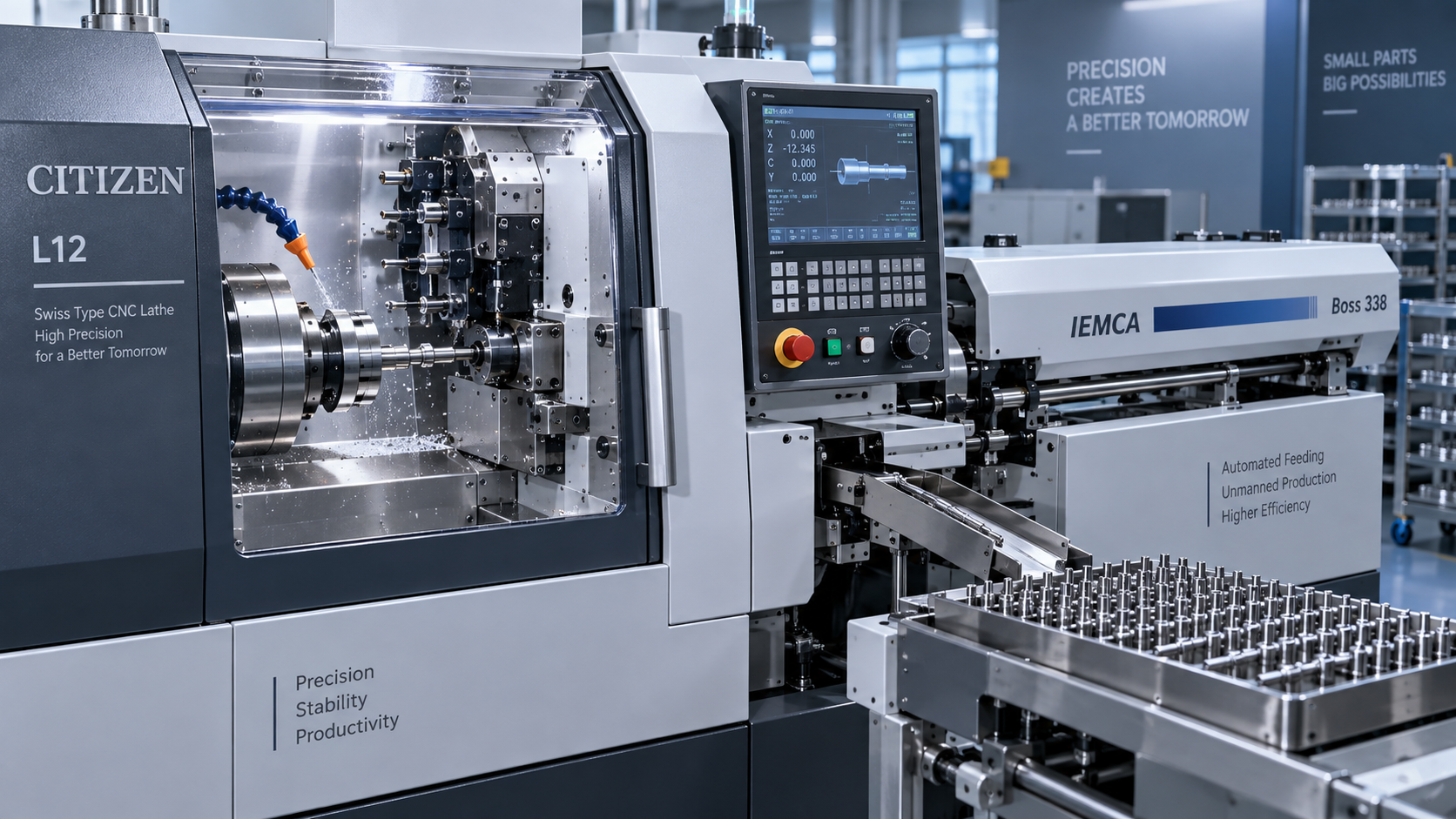
A small turned component can look simple on a drawing yet become difficult to produce once tolerances, burr limits, concentricity requirements, and takt time are applied together. A compact pin, threaded insert, watch-sized shaft, medical-style fitting, or electronic connector body may require several diameters, grooves, cross holes, and a controlled surface finish within one handling cycle. In that situation, selecting a machine only by maximum spindle speed or floor space often leads to a lathe that is fast in air but unstable in production.
The right CNC Lathe for Small Parts is the one that maintains required accuracy at the intended production rate, with the actual bar stock, tools, workholding, and automation method already considered. Start with the part family and process sequence, then evaluate spindle behavior, machine rigidity, axis response, tool layout, chip control, and unattended-operation readiness. A high nominal speed is useful only when the machine can use it without compromising runout, thermal stability, or tool life.
Begin with the finished part, not the machine brochure
Before comparing models, separate the part requirements into features that drive machine selection. This avoids paying for capacity that will not be used while overlooking a limitation that later creates secondary operations.
- Raw stock form: bar, slug, near-net blank, tube, or preformed forging. Bar-fed work usually points toward a collet-based configuration; short blanks may favor chucking or specialized loading.
- Maximum and minimum diameters: the minimum diameter can be as important as the maximum because slender features reveal limitations in guide bushing support, tailstock support, part ejection, and vibration control.
- Critical relationships: identify diameters or faces that must remain concentric, coaxial, perpendicular, or positionally related after machining.
- Feature sequence: note whether the part needs drilling, tapping, milling flats, cross drilling, polygon machining, engraving, or back-working after cutoff.
- Material behavior: free-machining brass, stainless steel, aluminum, alloy steel, titanium, and engineering plastics place very different demands on spindle torque, coolant delivery, chip evacuation, and tooling.
- Production pattern: distinguish between frequent low-volume changeovers and long, repeatable runs. The better machine architecture is not always the one with the shortest theoretical cycle.
A useful review method is to mark every feature as either “completed in the first clamping,” “completed after transfer,” or “requires a secondary operation.” Features that affect datum relationships should normally be kept in one controlled process whenever practical. A machine with a subspindle and synchronized transfer may cost more than a basic two-axis lathe, but it can eliminate handling variation and queue time where back-side accuracy matters.
Match the machine architecture to the part geometry
For simple bushings, spacers, pins, and short rotational components, a conventional two-axis CNC lathe with a collet chuck can be the most stable and economical option. Its strengths are straightforward setup, robust turning performance, and accessible tooling. It is less suitable when the part requires back-side finishing or multiple off-center features.
A gang-tool lathe is often attractive for small parts because tools sit close to the work zone. The short distance between tool stations and the part can reduce non-cutting time and improve stiffness. This arrangement works particularly well where the machining sequence is primarily turning, facing, grooving, drilling, and cutoff. Its limitation is tool capacity and geometry: as the process gains live-tool features, complex drills, or multiple redundant tools for unattended production, the layout can become crowded.
Turret lathes provide broader tool capacity and easier accommodation of live tooling, but turret index time and tool overhang need careful review. For a part with many tools but moderate quantity, the flexibility may justify the extra movement. For a high-volume part using only a few turning tools, a gang arrangement may deliver a more efficient cycle.
Swiss-type or sliding-headstock machines deserve consideration when stock is small in diameter and the unsupported length is significant. A guide bushing supports the work close to the cutting point, which can greatly improve control of slender shafts and long fine features. They also support overlapping operations through multiple tool zones and subspindle work. However, they add setup discipline: guide bushing selection, stock straightness, remnant length, and synchronization all affect the practical result. A Swiss-type platform is not automatically the best answer for every small component, especially short, rigid parts with limited complexity.
When evaluating a part family rather than one drawing, group parts by diameter range, material, operation count, and tolerance sensitivity. One versatile machine may cover the family, but forcing very different jobs onto one platform can cause avoidable setup and scheduling losses.
Accuracy is a system property, not a positioning claim
Published positioning accuracy and repeatability are important, but they do not by themselves predict finished-part capability. Small parts expose errors that may remain hidden on larger work. A few microns of collet runout, tool deflection, thermal drift, or transfer misalignment can consume a large portion of the available tolerance.
Ask how the machine holds accuracy during a realistic sequence, not merely after an axis calibration. The evaluation should include spindle warm-up behavior, repeated clamping of actual stock, representative cutting loads, coolant flow, and the time required to stabilize after a tool offset change. A machine may repeatedly position an axis well while still producing variable diameters because of spindle temperature, inconsistent stock, or cutting-force changes.
Spindle and workholding deserve early scrutiny
For small-diameter work, spindle runout at the collet seat and the condition of the drawtube system matter directly. A collet that is appropriate for one material or diameter range may not provide the same grip on thin-wall tubing, hard stock, or short protrusions. Review available collet styles, closing force control, changeover time, and whether the machine can detect a clamping issue before machining begins.
Spindle speed should be evaluated together with torque and acceleration. Tiny diameters may need high surface speed, particularly in aluminum or brass, while drilling and tapping can require torque at lower rpm. Constant surface speed capability is helpful, but rapid speed changes should not create excessive cycle penalties. For interrupted cuts, hard materials, or eccentric forms, prioritize spindle stability and bearing condition over a headline maximum rpm value.
Thermal control affects long runs
In a short prove-out, nearly any capable machine can produce an acceptable first-off part. Production stability is the harder test. Heat enters the system through the spindle, axes, hydraulic or pneumatic devices, coolant, and surrounding environment. As temperatures shift, tool center position and diameter can move. This is particularly relevant where a small feature has a narrow tolerance band or where both main and subspindle operations must remain aligned.
Assess the available thermal compensation strategy, but do not treat compensation as a substitute for sound mechanical design. Check whether spindle cooling, enclosure temperature management, and control compensation are suitable for the duty cycle. The machine should also provide practical offset management so operators can make controlled corrections without masking a developing problem.
Protect cycle time by separating cutting time from avoidable time
Small-part quotations often focus on spindle speed because cutting distances are short. Yet in many cycles, non-cutting motion has equal or greater influence: bar advance, turret indexing, tool approach and retract, part transfer, subspindle synchronization, probing, part ejection, and door movement can dominate the total.
Build an operation-by-operation time model before selecting equipment. It does not need false precision; its purpose is to expose where machine architecture changes the result. List each cut, tool change, work transfer, spindle stop, indexing event, and loading action. Then identify which activities can occur simultaneously. A machine with live tooling and dual spindles is valuable when it genuinely overlaps work, not simply because those functions are available.
Do not reduce every rapid move or dwell until the process becomes fragile. A very aggressive approach can increase tool shock, move chips into a critical zone, or cause a transfer sequence to become sensitive to minor stock variation. The productive target is a repeatable cycle that can run through normal variation, rather than the shortest cycle achieved during a closely watched demonstration.
Tooling capacity must support process control
Small parts usually need compact tools, but compact does not mean simple. A deep small-diameter hole may need a pilot, drill, reamer, and deburring method. A fine external thread may require a dedicated insert geometry and a backup tool. Where unattended operation is planned, duplicate tools can be worthwhile for managing wear or recovering from a damaged edge without immediately stopping the machine.
Review the machine’s usable tool envelope with actual holders installed. The nominal number of stations can be misleading if adjacent tools interfere, live-tool units consume neighboring positions, or long drills cannot be safely retracted. Confirm that toolholders provide adequate rigidity and coolant access at the required approach angle.
Tool offset handling is equally important. The control should make it clear which offsets affect diameter, length, wear, and geometry. In a high-mix environment, reliable program and offset management reduces the risk of carrying settings from one part to another. In a high-volume environment, monitoring predictable wear trends is more valuable than making frequent reactive corrections.
Chips and coolant can decide whether the cell runs unattended
Small components are vulnerable to chip-related failures. Stringy chips can wrap around small workpieces, interfere with cutoff, mark finished surfaces, block a part catcher, or prevent reliable probing. Fine chips can accumulate around collets and jaws, affecting seating and clamping. These are not peripheral housekeeping concerns; they affect dimensional consistency and uptime.
Examine coolant delivery at the cutting edge, not just pump specifications. Through-tool coolant may be important for small drills and deep bores. Directed nozzles can improve chip breaking during turning and grooving. Filtration should match both the material and the smallest process features, particularly when tiny orifices, coolant-fed tools, or precision hydraulic components are involved.
Also inspect the discharge path. A conveyor designed for large curled chips may not manage fine, wet material effectively. Chip evacuation, part separation, and coolant recovery should be reviewed as one system. A machine that cuts accurately but requires repeated manual clearing is not a high-throughput production platform.
Automation should be specified from the failure modes backward
Bar feeders, loaders, robots, and part catchers can reduce handling time, but the automation choice should follow the component and its risks. Bar-fed production is efficient for parts that start from standard round stock and can tolerate the remnant strategy. Short blanks or delicate finished surfaces may need tray handling, a robot, or a dedicated loading arrangement.
Identify what happens when the process does not run normally: a short bar, a crooked end, a part that sticks after cutoff, a chip on the collet face, a broken drill, or a full finished-parts container. The required sensors and recovery logic depend on these events. Automation that only works when every part behaves perfectly transfers labor from loading to troubleshooting.
For components with tight tolerances, consider where inspection belongs. In-process probing can confirm selected dimensions or tool conditions, but it takes time and must be protected from coolant and chips. Post-process gauging may be more appropriate for critical characteristics that cannot be reliably measured in the machine. The selection decision should account for this inspection time and the method used to prevent mixed or unverified parts from moving downstream.
A practical evaluation sequence before committing
Request a review based on representative production conditions rather than a generic machine demonstration. Provide drawings, tolerance callouts, material condition, expected lot sizes, annual volume pattern, surface requirements, and any secondary operations currently used. Include the difficult parts of the family, not only the easiest one.
- Map the proposed operation sequence and identify every datum-changing event.
- Check that spindle capacity, collet range, tool envelope, and axis travel cover the full part family with reasonable setup margins.
- Estimate cycle time by separating simultaneous work from sequential work and including loading, transfer, and ejection.
- Review how the machine maintains critical diameters and coaxial relationships after warm-up and through normal tool wear.
- Evaluate chip control using the actual material type and a realistic coolant approach.
- Determine the operator interventions expected per shift: bar changes, part collection, tool replacement, cleaning, gauging, and recovery from minor faults.
- Confirm service access for collets, guide bushings, filters, tooling, and routine maintenance, because difficult access can turn small recurring tasks into lost production time.
The final choice should reflect the dominant constraint. Choose a rigid, straightforward turning platform when the work is short and rotational. Move toward a subspindle when second-operation handling threatens datum control or flow. Consider a sliding-headstock design when slender geometry and overlap opportunities justify its added process complexity. In every case, the machine should be judged by stable finished parts over a sustainable cycle, not by its fastest isolated motion or its broadest option list.
NEXT ARTICLE
Recommended for You
 How to Select a CNC Lathe for Small Parts Without Sacrificing Accuracy or Cycle TimeCNC Machining Technology Center
 How to Select a Slant Bed Lathe for High-Precision Shaft and Chuck WorkCNC Machining Technology Center
 Smart Manufacturing for Small Businesses: Where Automation Delivers the Fastest ROIMachine Tool Industry Editorial Team
 How to Specify a CNC Lathe for High-Volume Automotive Shaft ProductionCNC Machining Technology Center
 How Automated Precision Machining Maintains Tolerance in High-Mix ProductionCNC Machining Technology Center
 How to Evaluate a Machine Tool Factory Before Sourcing CNC EquipmentGlobal Machine Tool Trade Research Center


Aris Katos
Future of Carbide Coatings
15+ years in precision manufacturing systems. Specialized in high-speed milling and aerospace grade alloy processing.
▶
How to Select a CNC Lathe for Small Parts Without Sacrificing Accuracy or Cycle TimeCNC Machining Technology Center▶
How to Select a Slant Bed Lathe for High-Precision Shaft and Chuck WorkCNC Machining Technology Center▶
How to Specify a CNC Lathe for High-Volume Automotive Shaft ProductionCNC Machining Technology Center▶
CNC Turning Explained: How It Works, Key Tolerances, and Best-Fit Part TypesCNC Machining Technology Center▶
Metal Lathe vs CNC Lathe: Which Is Better for Tolerance, Output, and Cost?CNC Machining Technology Center
Mastering 5-Axis Workholding Strategies
Join our technical panel on Nov 15th to learn about reducing vibrations in thin-wall components.

Providing you with integrated sanding solutions
Before-sales and after-sales services
Comprehensive technical support