• Global CNC market projected to reach $128B by 2028 • New EU trade regulations for precision tooling components • Aerospace deman
NYSE: CNC +1.2%LME: STEEL -0.4%

Space-Saving CNC Manufacturing: Shop Layout Strategies for Small Facilities
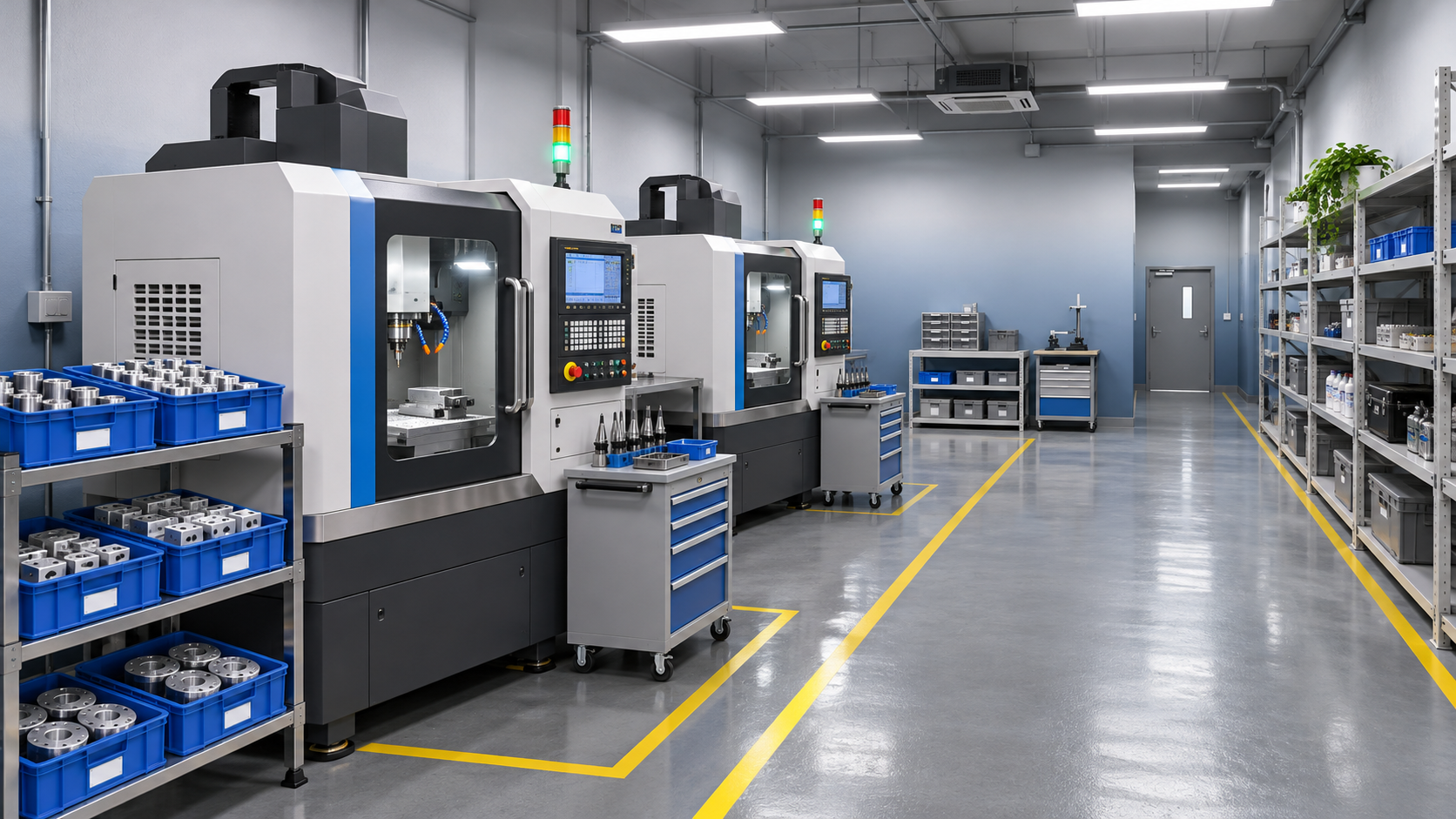
A small CNC facility can run out of usable space long before every square foot is occupied. A machine may fit on the drawing, yet its open door blocks an aisle, its bar feeder extends into a delivery route, or finished parts accumulate beside the next operation. These conflicts reduce access and make routine work harder to schedule.
Space-saving CNC manufacturing starts by arranging the complete production flow, not by packing machine footprints as tightly as possible. Map material movement, reserve operating and maintenance clearances, then compare equipment positions against the actual mix of parts, staffing, and planned automation. The best layout is the one that keeps work moving without turning access space into temporary storage.
Start with the part route, not the machine catalog
Before moving equipment or selecting a new machining center, trace the path of representative jobs through the facility. Include receiving, raw-material storage, cutting, machining, deburring, washing, inspection, packing, and dispatch where applicable. Record where material waits as well as where it is processed. Waiting locations often consume more useful floor area than the equipment list suggests.
Choose a few representative routes rather than trying to design around every exceptional job. A shop producing short batches of unrelated components may need flexible staging near several machines. A facility with recurring part families may benefit from grouping the machines and inspection resources used in their usual sequence. Neither arrangement eliminates all movement, but the route map exposes repeated crossings and unnecessary backtracking.
For each route, note the size and weight of the load, the handling method, and whether parts are carried individually or on pallets. A path suitable for a hand cart may not accommodate a loaded pallet jack turning safely. Heavy workpieces may also require crane or lifting access that is not visible in a simple machine-footprint plan.
Draw the space each machine actually needs
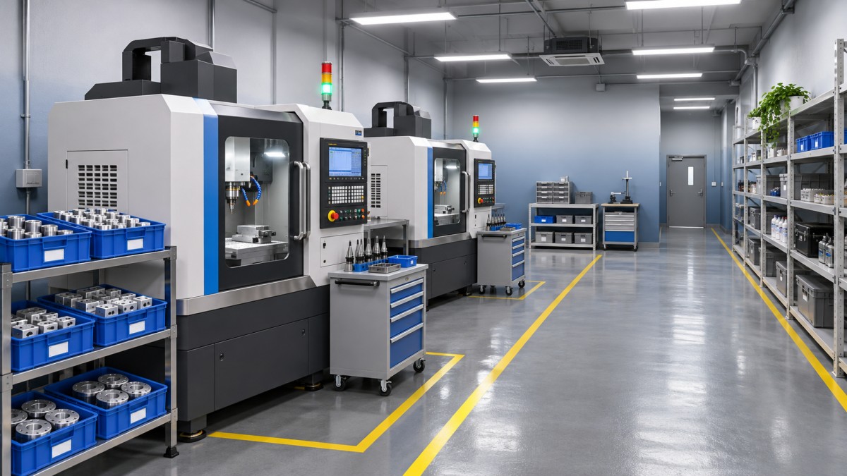
A machine’s published dimensions are a starting point, not a complete layout. Obtain the installation and service drawings for the intended configuration, including accessories, and mark the equipment on a scaled floor plan. Then add the areas needed during normal operation and maintenance.
- Operator access: Include door swing or travel, control-panel reach, loading position, and room to handle the largest expected workpiece or fixture.
- Material handling: Show the approach and turning space for carts, pallet jacks, forklifts, or lifting devices used at that machine.
- Maintenance: Allow access to electrical cabinets, lubrication points, coolant equipment, filters, chip removal, and components that must be inspected or replaced.
- Machine configuration: Add bar feeders, parts catchers, chip conveyors, coolant tanks, mist extraction, electrical cabinets, and any guarding or automation enclosure.
- Building constraints: Identify columns, doors, exits, electrical panels, sprinklers, drains, floor-loading limits, and utility connection points.
Keep these zones distinct on the drawing. Some circulation areas may serve more than one purpose at different times, but a required service area should not be treated as permanent storage. Check the proposed clearances against the equipment supplier’s instructions and applicable local safety and building requirements; an attractive drawing does not override either.
Also consider installation and removal. A machine may fit in its final position but be impossible to bring through a doorway or maneuver around a column. Check rigging routes, overhead obstructions, floor capacity, and the space needed to remove major components before committing to the arrangement.
Choose a layout around flow and variability
Three arrangements are particularly useful in small facilities. Their suitability depends less on the number of machines than on how work travels between them.
A hybrid can be more practical than forcing the whole shop into one pattern. Frequently paired turning and milling operations, for example, can be located near each other while a shared inspection area remains accessible to other routes. Avoid positioning machines solely by process name: two lathes may belong together on a list but have very different material-handling needs if one uses bar stock and the other handles large castings.
Test each option with a representative job. Walk the route on the drawing from incoming stock to completed part, including fixture changes and inspection. Mark each crossing of a main aisle and each point where a cart must be parked. A shorter theoretical distance is not an improvement if it creates a blind corner or requires loads to pass through an operator’s working area.
Make staging a controlled part of the layout
Work in process needs a defined home. Without one, pallets and containers tend to occupy the nearest open space, including access to machine doors and electrical cabinets. Assign a bounded staging area to each critical handoff and decide what belongs there: raw blanks, parts awaiting inspection, or completed batches, for example. Clear identification helps prevent mixed lots as well as floor congestion.
Set a practical limit based on container size and the handling method. When the area is full, treat that as a signal to review release timing, batch size, or the capacity of the next operation rather than opening another informal storage location. The limit should support the production schedule, not simply move excess inventory into an aisle.
Point-of-use storage can reduce walking, but only for items that are actually used at that station. Keep common tools, gauges, and fixtures accessible without obstructing the operator or the machine’s service panels. Less frequently used fixtures can move to a shared location with an inventory system that makes them easy to find.
Use vertical storage with the handling task in mind
Racks and cabinets can release floor space, especially for standardized tooling and light supplies. Their value depends on what can be retrieved safely. Heavy chucks, tombstones, and fixture plates may need low-level storage or a suitable lifting method; placing them high to create an empty floor is not a workable improvement. Confirm rack capacity, anchoring where required, load stability, and access for inspection before moving material upward.
Evaluate compact equipment by the whole work envelope
A smaller machine can make room for another operation, but only if it can handle the required parts, tooling, and duty. Compare usable travels, spindle and chuck capacity, tool capacity, workholding, chip evacuation, and access for loading against the intended job family. A compact enclosure that requires frequent external setup or unusually large material-handling space may save less floor area than expected.
Combining operations on a multi-axis machining center or a turning center with milling capability can reduce transfers and intermediate staging. That approach is most attractive when the parts genuinely need those capabilities and the required fixtures can be loaded efficiently. It can also concentrate work on one machine, making maintenance or an extended setup more disruptive to the schedule. Compare the full route and available backup capacity, not just the number of machines removed from the drawing.
Similarly, a bar feeder may reduce manual loading for suitable turned parts, but its length, stock-loading direction, and access requirements must be included from the beginning. Chip conveyors and coolant systems deserve the same treatment: their discharge and service positions can dictate aisle placement even when the machine itself fits neatly against a wall.
Reserve space for automation before buying it
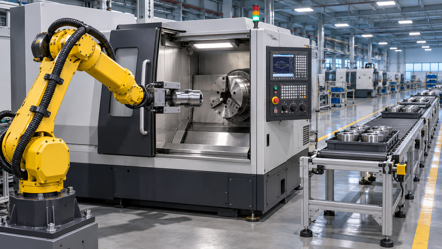
Automation can change the shape of a small shop. A robot or pallet system needs more than a mounting point: its reach, guarding, loading interface, part presentation, recovery access, and maintenance zones all affect the layout. Draw the complete proposed cell, including the location where an operator replenishes blanks and removes finished parts. Confirm that normal replenishment does not block the neighboring machine or a shared route.
Choose the level of automation against the production pattern. A recurring family of parts may justify a dedicated loading arrangement, while a high-mix environment may need quicker changeover and adjustable workholding. A compact machine-tending cell is not useful if each new part requires extensive rearrangement or if there is no practical place for the next batch of blanks.
Where automation is planned for a later phase, protect the likely equipment envelope and utility route now. That does not require buying the system immediately, but it does mean avoiding permanent cabinets, drains, or fixed storage in the proposed location until the concept has been checked. Confirm power, air, network connections, extraction, and control interfaces with the relevant equipment suppliers before treating the space as automation-ready.
Validate the plan against a working shift
A scaled drawing can reveal conflicts, but the layout should also be tested against the tasks performed during a shift. Use floor markings or removable templates to represent equipment, open doors, staging boundaries, and handling paths. Walk through loading a large workpiece, changing a fixture, removing chips, inspecting a part, and accessing a machine that is out of service. Include the people who perform those tasks; a service panel that looks reachable on paper may be blocked by a cart in normal use.
Check simultaneous activity rather than one movement at a time. An operator may be tending one machine while another person replenishes material or a maintenance technician opens a cabinet. Identify where those activities compete for the same space and decide whether they can be scheduled separately or require a layout change. Keep exits, access routes, and safety equipment unobstructed throughout the test.
Once the layout is in use, observe where material accumulates, which routes are repeatedly obstructed, and which tools migrate away from their assigned locations. Those are practical signs that the plan needs adjustment. A defined staging boundary, a relocated rack, or a different machine orientation may resolve a bottleneck without another equipment purchase.
Recommended for You
![]() Perpetua Resources Signs MOU to Evaluate US Tungsten Supply ChainManufacturing Market Research Center
 Choosing an Automated Lathe: Bar Capacity, Accuracy and Production VolumeCNC Machining Technology Center
![]() US Cutting Tool Shipments Reach $287.6 Million in September 2026Machine Tool Industry Editorial Team
 Choosing a Machine Tool Supplier: Service, Lead Times and Total CostManufacturing Market Research Center
![]() India Announces Domestic Five-Axis CNC Machine With 2-Micron AccuracyMachine Tool Industry Editorial Team
 Integrating Industrial Automation into Existing Production Lines: Key StepsMachine Tool Industry Editorial Team


Aris Katos
Future of Carbide Coatings
15+ years in precision manufacturing systems. Specialized in high-speed milling and aerospace grade alloy processing.
▶
Which Metals Are Hardest to Machine With Standard Tools, and Why?CNC Machining Technology Center▶
Space-Saving CNC Manufacturing: Shop Layout Strategies for Small FacilitiesCNC Machining Technology Center▶
CNC Milling Spindle Speed for Titanium: How to Calculate RPMCNC Machining Technology Center▶
CNC Machine Tool Accuracy Standards Compared: ISO 230 vs. ASME B5.54CNC Machining Technology Center▶
FANUC Links FIELD System Data with Copilot to Advance Shop-Floor Data UseCNC Machining Technology Center
▶
Mastering 5-Axis Workholding Strategies
Join our technical panel on Nov 15th to learn about reducing vibrations in thin-wall components.

Providing you with integrated sanding solutions
Before-sales and after-sales services
Comprehensive technical support