• Global CNC market projected to reach $128B by 2028 • New EU trade regulations for precision tooling components • Aerospace deman
NYSE: CNC +1.2%LME: STEEL -0.4%

What Tool Life Can You Expect from Ceramic Inserts?
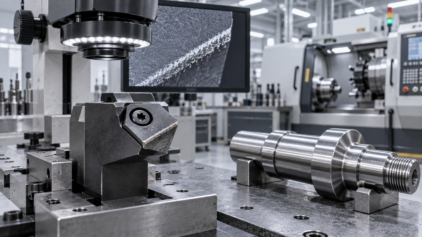
Ceramic inserts can deliver useful edge life at cutting speeds that would quickly wear an unsuitable carbide grade, but there is no reliable, universal answer in minutes or parts per edge. A stable cut in a compatible material may produce gradual, predictable wear. The same insert exposed to vibration, a hard interruption, or unsuitable coolant delivery may chip before completing a pass.
If you are asking “what tool life can I expect with ceramic inserts,” the most useful starting point is the life of one cutting edge under your actual production conditions. Judge that life against an agreed wear limit, dimensional tolerance, and surface requirement. Then compare the number of acceptable parts and machining time delivered by each edge. A ceramic that lasts fewer cutting minutes can still be economical if it removes material faster and changes reliably.
Can you predict tool life before running a trial?
You can assess whether an application is promising, but a dependable replacement interval requires cutting evidence. “Ceramic insert” covers several material families with different strengths. Workpiece alloy, hardness, surface condition, insert geometry, and the continuity of the cut all affect the result. A life figure from another operation has limited value unless those conditions are reasonably comparable.
Supplier application data can provide an initial cutting window. It is most useful when it identifies the specific grade, workpiece condition, operation, and criterion used to end the test. A reported life based on visible flank wear does not necessarily predict how long your process will hold a tight diameter or an acceptable surface finish.
Before treating any quoted life as a production target, establish these details:
- The exact workpiece material, including hardness or heat-treatment condition.
- The ceramic grade, edge preparation, insert shape, and toolholder arrangement.
- Cutting speed, feed, depth of cut, and whether the tool encounters interruptions.
- Coolant practice and the definition of an exhausted edge.
Without that information, a claim that an insert “lasts twice as long” offers little help. It may describe a different wear limit, a less demanding finish, or a cut with much better stability.
Which applications offer the best chance of predictable life?
Ceramics are attractive where their resistance to heat and wear suits the workpiece and where the machine can maintain a stable cut. Cast iron, hardened steel, and some heat-resistant alloys are relevant applications, but they require different ceramic grades and operating conditions.
Cast iron
Some ceramic grades are well suited to cast-iron machining, particularly when the workpiece and setup allow consistent engagement. Silicon nitride-based ceramics are one option in this area. Their suitability still depends on the particular iron, its structure, and the severity of any interrupted cutting.
Casting skin, inclusions, variable stock allowance, and local hard areas can make edge life less predictable. A trial on a cleaned, uniform surface may therefore overstate the life available when machining an as-cast component. Test the surface condition the tool will actually encounter.
Hardened steel
Appropriate ceramics can serve in hard turning, especially where a rigid setup and controlled engagement support the edge. Here, the usable life may end because surface finish or size drifts beyond the part requirement while the insert still appears capable of cutting.
Interrupted surfaces, slender parts, and weak workholding deserve close attention. Compare suitable ceramic and other hard-turning tool options against the actual quality requirement; a broad material label alone cannot determine the better choice.
Heat-resistant alloys
Selected ceramics, including certain reinforced alumina and SiAlON grades, are used for machining heat-resistant alloys. These applications can exploit high cutting speeds, but notch wear, edge damage, and workpiece surface condition can constrain life.
Success on one nickel-based alloy should not be carried across automatically to another alloy or heat treatment. For critical components, the tool also needs to maintain any specified surface-integrity requirements throughout its usable life. An acceptable-looking finish is not always sufficient evidence.
What should count as the end of tool life?
Tool life should end at the first condition that makes continued cutting unacceptable. Waiting until the insert breaks gives a poor basis for planning production and may damage the workpiece, holder, or subsequent process.
For roughing, the endpoint might be a defined wear condition, unstable cutting, or loss of stock-removal capability. For finishing, dimensional drift or surface deterioration can become limiting much earlier. Where inspection requirements include surface integrity, those requirements also belong in the tool-life definition.
Keep three measures distinct:
- Cutting time per edge: accumulated time actually engaged in material.
- Acceptable parts per edge: completed parts meeting the agreed requirements.
- Elapsed replacement interval: production time between changes, including loading, positioning, and other non-cutting activities.
These measures answer different questions. Cutting time helps compare wear behavior. Parts per edge supports purchasing and production planning. The replacement interval helps organize machine operation. Mixing them can make one tooling option appear more durable than it is.
Also distinguish an insert from an edge. An insert may provide several usable edges, but damage to a seat or an adjacent edge can reduce the number available. Cost calculations should use the edges actually consumed successfully.
What does the wear pattern tell you about expected life?
A consistent wear pattern makes life easier to predict. Sudden fracture creates a different problem: even a respectable average may conceal failures that make unattended production impractical. Inspect the insert alongside the machined surface and any changes in sound, load, or dimensional behavior.
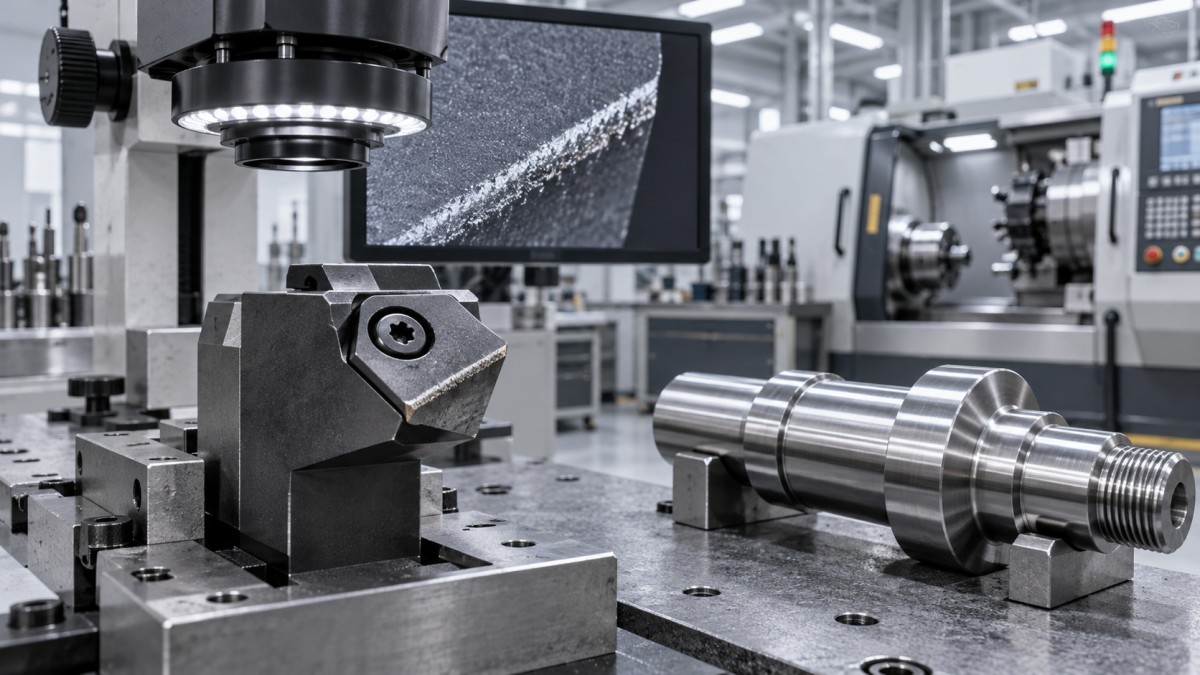
Progressive flank wear can provide a manageable route to scheduled replacement when it develops consistently. Track its relationship to part size and finish. The practical wear limit is the point at which the operation loses its required capability, which may occur before the edge looks severely worn.
Notch wear at the depth-of-cut line can shorten life, particularly in demanding alloy applications. Workpiece surface condition, work hardening, and repeated engagement at the same boundary may contribute. Depending on the operation, changing the cutting strategy or selecting a more suitable grade may help.
Small edge chips suggest that mechanical loading, stability, or edge strength needs investigation. Check insert seating, holder overhang, workholding, stock variation, and entry into the cut. Increasing edge strength may help, but a stronger edge preparation can also raise cutting forces.
Cracking or sudden breakage calls for a review of interruptions, thermal cycling, coolant delivery, and mechanical shocks. The appearance of a failed edge alone may not identify the cause. Combine inspection with the point in the toolpath where failure occurred and the conditions present at that moment.
Repeated premature failure should not be accepted as a normal wear rate. It can indicate that the grade, geometry, setup, or application is unsuitable.
How do speed, feed, and coolant change tool life?
Cutting speed strongly influences temperature and wear, but lowering speed is not an automatic cure. Ceramics have application-specific operating windows. Running outside the recommended window can leave the process inefficient or expose it to unfavorable cutting behavior. Start with guidance for the exact grade and workpiece, then adjust using observed results.
Feed and depth of cut affect chip formation, cutting forces, edge loading, and the position of the depth-of-cut boundary. An excessively light cut may introduce rubbing under some conditions, while an aggressive cut can overload the edge or excite vibration. Change one variable at a time when diagnosing a problem so that the result remains interpretable.
Coolant practice requires particular care. Some ceramic operations are run dry; others use coolant under grade- and application-specific recommendations. Intermittent delivery can impose thermal cycling and contribute to cracking in susceptible conditions. Follow the tooling guidance and maintain the chosen delivery method consistently through the cut.
Machine capability can be the limiting factor. Available spindle speed, power, rigidity, and control of entry and exit all influence whether the intended cutting conditions are achievable. A nominal speed programmed into the control is of little value if the process vibrates or repeatedly overloads the edge.
How should you establish a production replacement interval?
Run a trial that represents the job you intend to produce. Use the actual material condition, holder, workholding, coolant practice, and toolpath. Include difficult features such as casting skin or interruptions when they are part of normal production.
Set the acceptance criteria before cutting. Record accumulated cutting time, completed good parts, relevant dimensions, surface quality, and visible edge condition at planned inspection points. Keep enough detail to identify whether life ended through gradual wear or an unexpected failure.
Evaluate several edges under comparable conditions. One successful edge shows that the operation can work; it does not establish repeatability. Likewise, a single damaged edge may reflect an isolated seating or stock problem. Investigate anomalous results before combining them into a general life estimate.
For illustration, suppose a trial edge produces 20 acceptable parts, with 30 seconds of cutting engagement per part. That represents 10 minutes of accumulated cutting time. If a second process makes those parts with shorter engagement, its parts-per-edge result could improve without any increase in minutes of edge life. These are hypothetical figures, but the distinction matters when comparing tools.
Choose the scheduled change point with allowance for the variation observed in the trial and the consequences of failure. A stable process showing gradual wear can support a different margin from one producing occasional early chips. Reassess the interval when material condition, stock allowance, toolpath, or cutting parameters change.
Is longer edge life always the better economic result?
Longer life is valuable when it improves output or reduces cost without compromising quality. It is less useful when achieved through a large reduction in cutting speed that increases machine time.
Compare tooling cost per acceptable part, machining time, tool-change effort, inspection needs, and losses from rejected parts or unexpected stops. A ceramic edge that lasts fewer minutes than a carbide edge may still produce more acceptable components during its life because it cuts faster. Conversely, a fast process with erratic breakage may lose that advantage through downtime and scrap.
For automated production, consistency can be more valuable than the longest isolated result. A repeatable change interval allows the process to finish its planned cycle with confidence. Extending use close to the failure point only helps if the additional output exceeds the associated losses.
The useful answer to expected ceramic tool life is therefore an application-specific statement: this grade, in this material and setup, produces this many acceptable parts before a defined limit, with an observed degree of variation. Once that statement is supported by a representative trial, it becomes a practical basis for scheduling edge changes and judging whether ceramics improve the job.
PREVIOUS ARTICLE
Recommended for You
![]() Report: 56% of China's Key Steelmakers Lost Money in SeptemberManufacturing Market Research Center
 Machine Tool Prices: Is a CNC Upgrade Worth the Investment?Manufacturing Market Research Center
![]() China's Official Manufacturing PMI Falls to 49.3 in OctoberManufacturing Market Research Center
 CNC Machine Tool Accuracy Standards Compared: ISO 230 vs. ASME B5.54CNC Machining Technology Center
![]() Li Daokui: China Overtakes Germany With 21.6% of Global Machine Tool ExportsGlobal Machine Tool Trade Research Center
 Machine Tool Prices: What to Budget Beyond the Purchase PriceGlobal Machine Tool Trade Research Center


Aris Katos
Future of Carbide Coatings
15+ years in precision manufacturing systems. Specialized in high-speed milling and aerospace grade alloy processing.
▶
Choosing machining tools for thin-wall electronics housingsCNC Machining Technology Center▶
What Tool Life Can You Expect from Ceramic Inserts?CNC Machining Technology Center▶
Can Inconel Be Machined Without Excessive Tool Wear?CNC Machining Technology Center▶
Which Metals Are Hardest to Machine With Standard Tools?CNC Machining Technology Center▶
How to Choose Cutting Tools for High-Speed Machining of Steel, Aluminum, and TitaniumCNC Machining Technology Center
▶
Mastering 5-Axis Workholding Strategies
Join our technical panel on Nov 15th to learn about reducing vibrations in thin-wall components.

Providing you with integrated sanding solutions
Before-sales and after-sales services
Comprehensive technical support