• Global CNC market projected to reach $128B by 2028 • New EU trade regulations for precision tooling components • Aerospace deman
NYSE: CNC +1.2%LME: STEEL -0.4%

Can Inconel Be Machined Without Excessive Tool Wear?
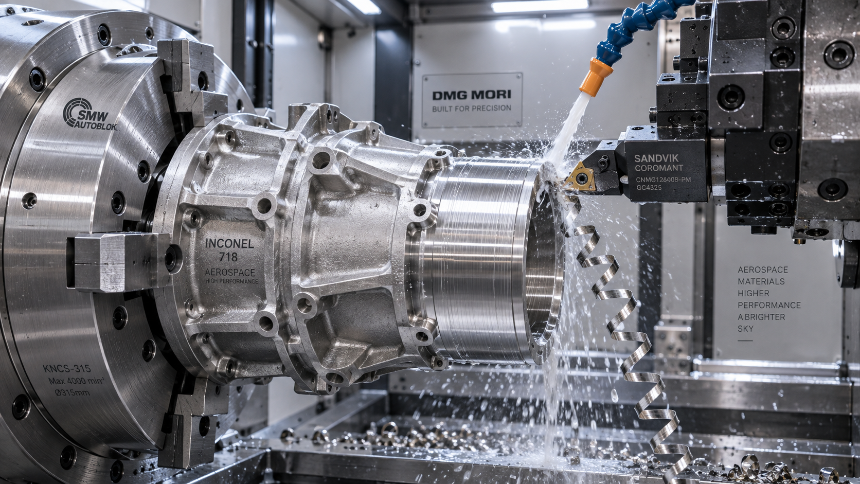
Yes—Inconel can be CNC machined without excessive tool wear, but not without wear altogether. The practical goal is a predictable tool-change interval that preserves dimensions, surface integrity, and production cost. When an aerospace housing or energy-system component starts consuming inserts unexpectedly, the cause is often a mismatch between the material condition, cutting edge, toolpath, coolant delivery, and setup rigidity—not simply the alloy name.
So, can metal machining handle Inconel without tool wear issues? It can avoid many premature failures, provided the process limits rubbing, manages cutting heat, and keeps the edge consistently engaged. A process that works on stainless steel should not be transferred unchanged to Inconel: rapid edge damage can lead to dimensional drift, poor finish, scrapped parts, and unplanned stoppages.
What makes Inconel wear out cutting tools so quickly?
Inconel is a family of nickel-based alloys, not a single material specification. Grades such as 625 and 718 differ in composition, strengthening mechanisms, and typical delivery conditions. Heat treatment can substantially change cutting forces and tool-life expectations, so the grade and material condition must be established before selecting parameters.
Several wear mechanisms can occur together. Relatively low thermal conductivity concentrates heat near the cutting zone, while strength retained at elevated temperatures increases demands on the edge. Adhesion can pull material from the tool surface. Hard constituents can contribute to abrasion, and repeated deformation can leave a work-hardened layer that makes the next cut more difficult.
Work hardening becomes especially troublesome when a tool rubs instead of forming a chip. A light cleanup pass, a dwell against the surface, or an underfed milling tooth can deform the material without removing it effectively. The next pass then encounters a harder surface with an already stressed cutting edge.
This explains why “slow everything down” is not a complete solution. Lower cutting speed may reduce thermal wear, but reducing feed too far can increase rubbing. The objective is to control temperature while maintaining chip formation.
Read the failed edge before changing the program
A worn insert is evidence. Inspect it under magnification and record where the damage occurs, whether it develops gradually, and which operation precedes failure. Replacing every damaged edge with a tougher grade can conceal the actual cause and reduce productivity unnecessarily.
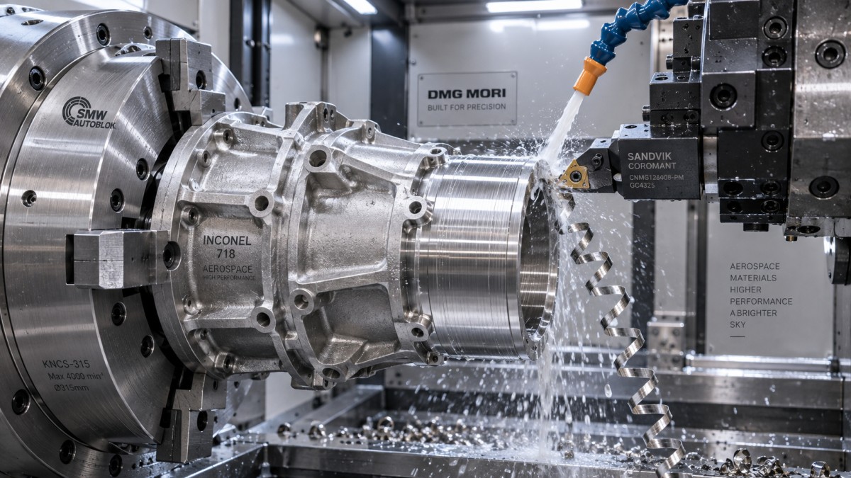
These observations indicate where to investigate; they do not prove a single cause. An insert may show both notching and chipping, for example. Establish which damage appears first rather than diagnosing only the final fracture.
Which cutting tools are appropriate?
Coated carbide is a common starting point for many Inconel turning, milling, and drilling operations. Choose a grade and geometry explicitly recommended for nickel-based heat-resistant superalloys. A tool intended primarily for general steel cutting may lack the balance of hot hardness, edge strength, and adhesion resistance needed here.
Geometry matters as much as the coating label. A positive cutting geometry can reduce forces, but an excessively sharp or weak edge may chip under interrupted engagement. A stronger edge preparation can resist breakage, yet too much honing may encourage rubbing at low chip thickness. Selection should reflect the operation: stable external turning and interrupted milling impose different demands.
Toolholder stability also affects whether the selected edge performs as intended. Use the shortest practical overhang, clean seating surfaces, and appropriate clamping. In milling, excessive runout loads one tooth more heavily than the others, creating premature failure even when the programmed feed appears reasonable.
Are ceramic inserts a better choice than carbide?
Ceramics can be productive in selected Inconel operations, particularly stable rough turning and specialized milling applications. Their temperature capability permits cutting strategies outside normal carbide practice. However, brittleness, engagement conditions, surface-integrity requirements, and machine capability limit their suitability.
They are not a direct replacement using the same program and coolant settings. Some ceramic applications use dry cutting to avoid thermal shock; others require application-specific guidance. Follow the tool supplier’s recommendations for the ceramic grade, operation, and coolant strategy. For flexible production involving interrupted cuts or demanding finishing, carbide may remain the more manageable option.
Set parameters around chip formation, not just spindle speed
There is no universal Inconel speed-and-feed setting. Begin with the tooling supplier’s recommendations for the confirmed alloy condition, tool diameter, cutting geometry, and operation. Then assess actual engagement, machine rigidity, and coolant capability before moving toward a more aggressive operating point.
Three adjustments deserve particular attention:
- Cutting speed: Excessive speed can accelerate thermal wear. A controlled reduction is often worth testing when edge deformation or crater wear dominates.
- Feed and chip thickness: Keep the edge cutting rather than rubbing. During low-radial-engagement milling, account for chip thinning instead of assuming programmed feed per tooth equals maximum chip thickness.
- Depth and width of cut: Set engagement to suit the tool and setup. Increasing engagement without checking forces can cause deflection or fracture; making every pass extremely shallow can repeatedly work the same hardened surface.
Actual feed may fall below the programmed value when a machine negotiates short segments, tight corners, or acceleration-limited motion. Inspect these regions when wear is concentrated around features rather than distributed across the whole operation. Raising the programmed feed alone will not necessarily correct controller-induced slowing.
Can coolant alone solve premature wear?
No. Coolant cannot compensate for chatter, an unsuitable edge, or a toolpath that repeatedly overloads the cutter. It can, however, make a substantial difference when delivered reliably to the cutting zone.
For suitable carbide applications, through-tool or accurately directed coolant can improve access to the tool–chip interface and assist chip evacuation. High-pressure delivery may improve chip control in some operations, but its effectiveness depends on nozzle position, flow, tool design, and chip geometry. A pressure rating by itself says little about what reaches the edge.
Confirm coolant concentration against the fluid supplier’s guidance, maintain filtration, and check for blocked passages or misaligned nozzles. Deep holes and enclosed pockets deserve special attention because retained chips can be recut, jam flutes, and damage an otherwise appropriate tool.
Intermittent coolant contact can create damaging temperature fluctuations in sensitive applications. Establish a consistent delivery strategy rather than allowing the edge to alternate unpredictably between wet and dry conditions. Ceramic tooling requires separate consideration; do not assume a carbide coolant practice is transferable.
Toolpaths and workholding: where preventable failures begin
A milling cutter may perform well in a straight cut and fail at the first internal corner. The engagement angle rises, more of the edge contacts the material, and cutting forces increase abruptly. A toolpath designed to maintain more consistent engagement can reduce these peaks, provided its feed settings account for the resulting chip thickness.
Use controlled entries rather than abrupt plunges unless the tool is designed for them. Avoid unnecessary dwelling against the finished surface. Position retracts and transitions so the cutter does not drag across the workpiece. Chip evacuation must remain effective throughout the pocket, not only near its opening.
In turning, repeated cutting at one depth-of-cut boundary can promote localized notching. Where geometry and allowances permit, varying that boundary may spread the damage. This needs deliberate planning: random depth changes can introduce force variation and compromise dimensional control.
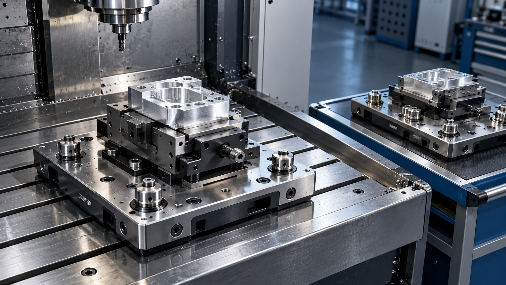
Workholding should restrain the component close to the cut without distorting it. Thin walls, long shafts, and slender tools introduce compliance that cannot be corrected by selecting a tougher insert alone. Support the workpiece appropriately, shorten overhang where possible, and review the machining sequence so that critical cuts occur before unnecessary loss of stiffness.
How do you establish an acceptable tool-change interval?
“Excessive wear” should be defined by part requirements and process cost, not appearance alone. A visibly worn edge may still produce conforming roughing cuts, while a less damaged finishing edge may already cause unacceptable size drift or surface defects.
- Confirm the baseline. Record alloy grade, heat-treatment condition, stock surface, tool specification, holder, coolant setup, and program revision.
- Run a controlled trial. Keep the initial setup constant and inspect the edge at planned intervals rather than waiting for failure.
- Track part quality alongside wear. Check critical dimensions, finish, burr formation, and any required surface-integrity criteria.
- Change one meaningful variable. Test speed, grade, engagement, or coolant delivery separately so the effect can be interpreted.
- Set the replacement point before quality becomes unstable. Confirm it across repeated edges and representative production conditions, including difficult features.
Measure cutting exposure consistently. Parts per edge can be useful for an unchanged component, but cutting time and removed material help compare different operations. Spindle-load trends may support monitoring, although they should not replace edge inspection and dimensional checks.
Assess total cost per conforming part. A more expensive tool can be economical if it reduces stoppages and scrap; a longer-lasting edge may still be unattractive if it requires excessively slow machining.
Additional shop-floor questions
Should roughing and finishing use separate tools?
Often, yes. A roughing edge can accumulate damage that makes a final pass unpredictable. Reserving an edge for finishing improves control over its condition. Leave a consistent finishing allowance that supports cutting without excessive force or rubbing; an extremely small skim is not automatically gentler.
Can Inconel be machined before final heat treatment?
In some manufacturing routes, rough machining in a more machinable condition is practical. The drawing, heat-treatment sequence, distortion allowance, and final material requirements determine whether this is acceptable. Leave sufficient stock for correction afterward, and do not change the specified processing route solely to improve tool life without approval.
When is further process validation necessary?
Escalate beyond routine parameter tuning when tools fracture unpredictably, critical surfaces show damage, or dimensions remain unstable despite a rigid setup. For fatigue-critical components, a smooth-looking surface alone is insufficient evidence of acceptable integrity. Follow the component’s specified inspection and process-qualification requirements before releasing a revised machining strategy.
PREVIOUS ARTICLE
Recommended for You
![]() JTEKT Introduces G5 Series Large CNC Cylindrical Grinder, Sales Begin October 26, 2026Machine Tool Industry Editorial Team
 Shaft Parts for Heavy Machinery: Selecting Materials for High Shock LoadsCNC Machining Technology Center
![]() 33rd JIMTOF 2026 Set to Open in Tokyo as Taiwanese Exhibitors Seek OrdersGlobal Machine Tool Trade Research Center
 Which Fixture Type Cuts Changeover Time Most in High-Mix CNC Machining?CNC Machining Technology Center
![]() FANUC Invests $18 Million in Largest U.S. Corporate Automation Training CenterMachine Tool Industry Editorial Team
 Southeast Asia Machine Tool Market: Comparing Automotive Demand by CountryManufacturing Market Research Center


Aris Katos
Future of Carbide Coatings
15+ years in precision manufacturing systems. Specialized in high-speed milling and aerospace grade alloy processing.
▶
Choosing machining tools for thin-wall electronics housingsCNC Machining Technology Center▶
Can Inconel Be Machined Without Excessive Tool Wear?CNC Machining Technology Center▶
Which Metals Are Hardest to Machine With Standard Tools?CNC Machining Technology Center▶
How to Choose Cutting Tools for High-Speed Machining of Steel, Aluminum, and TitaniumCNC Machining Technology Center▶
How to Choose a CNC Tooling System for Titanium Machining by Tool Life and StabilityCNC Machining Technology Center
▶
Mastering 5-Axis Workholding Strategies
Join our technical panel on Nov 15th to learn about reducing vibrations in thin-wall components.

Providing you with integrated sanding solutions
Before-sales and after-sales services
Comprehensive technical support