• Global CNC market projected to reach $128B by 2028 • New EU trade regulations for precision tooling components • Aerospace deman
NYSE: CNC +1.2%LME: STEEL -0.4%

Choosing machining tools for thin-wall electronics housings
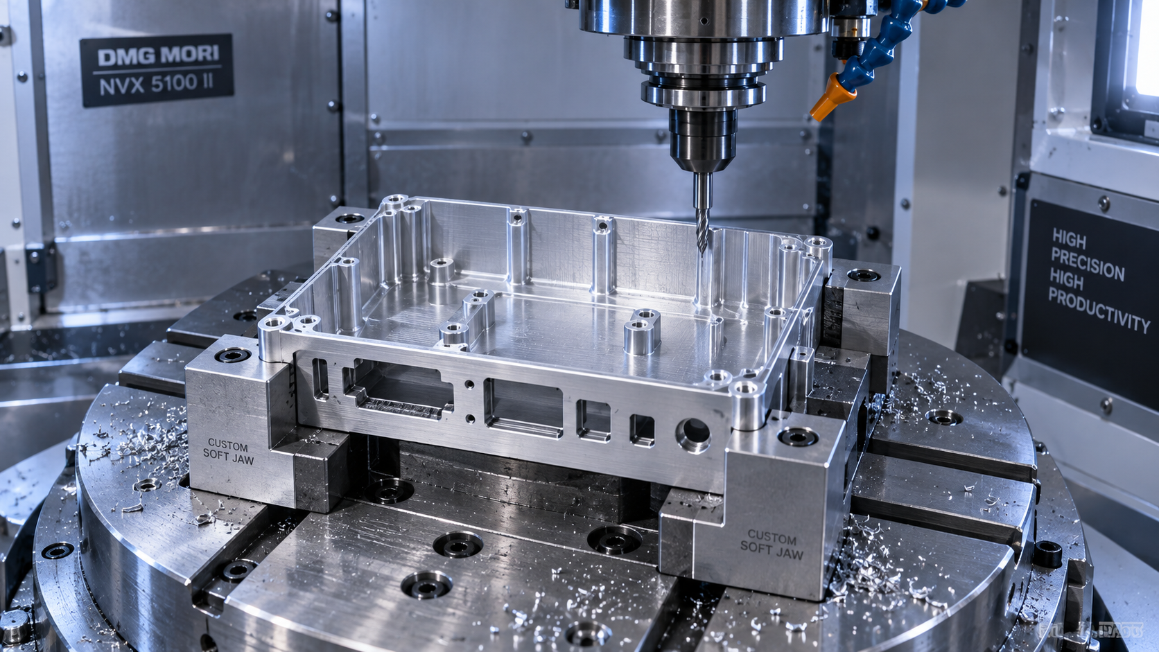
A thin-wall electronics housing can look excellent while it is still clamped to the machine table—and then move out of tolerance when released. Another may hold its dimensions but arrive at inspection with burrs around connector openings or chatter marks across a visible sidewall. These failures often lead evaluators to question the cutter, even when the real problem lies in the interaction between tooling, workholding, and machining sequence.
For technical teams comparing electronics manufacturing tools for machining, the objective is not simply to find an end mill that cuts quickly. It is to select a tooling system that controls cutting forces, evacuates chips, reaches delicate features, and produces repeatable results as the housing becomes less rigid. The right choice depends as much on the finished wall geometry as it does on the material being removed.
Start with the housing’s weakest feature, not the tool catalog
Before comparing cutter specifications, identify where the part is most vulnerable. A broad unsupported sidewall behaves differently from a short rib, a deep pocket, or a narrow bridge between ventilation slots. Wall height, thickness, corner geometry, and distance from the nearest support all influence how much a feature moves under cutting load.
There is no universal wall thickness below which machining becomes “thin-wall machining.” A relatively thick but tall, unsupported wall can be more troublesome than a thinner wall supported along several edges. The useful question is: how compliant is this feature at the moment it is being cut?
Build the tooling requirements around a short feature review:
- Structural features: tall walls, thin floors, ribs, and isolated mounting bosses.
- Functional interfaces: sealing lands, connector apertures, threaded holes, and mating surfaces.
- Cosmetic surfaces: exposed faces where chatter, scratches, or uneven deburring will remain visible.
- Access constraints: deep pockets, small internal radii, and features that require long tool reach.
Also confirm when dimensions and appearance will be judged. Anodizing or another surface treatment may affect fit and reveal machining marks. Tool selection should therefore reflect the finished-part requirements, not only the drawing dimensions before treatment.
Match cutting geometry to the material—and the wall
A geometry that performs well in a rigid test block may behave poorly on a flexible housing. For thin walls, the balance between cutting-edge sharpness and edge strength deserves particular attention.
Aluminum housings: sharp edges and reliable chip clearance
For many wrought aluminum alloys, polished flutes, positive rake, and sharp cutting edges are useful starting points. They reduce the tendency to smear material and help limit built-up edge, which can increase cutting forces and damage the finish. Two- or three-flute end mills are common choices for pocketing because they provide generous chip space, although the best flute count depends on engagement and available feed.
More flutes are not automatically better. A higher-flute-count tool may offer a stronger core and greater finishing productivity, but restricted chip space can become a liability in deep pockets. Recut chips can scratch a wall or initiate an unstable cut.
Coating selection should be alloy-specific. Uncoated polished carbide and aluminum-compatible coatings are both viable options; neither is universally superior. Abrasive, high-silicon aluminum may justify diamond-coated or polycrystalline diamond tooling in suitable operations. Evaluate wear resistance alongside edge sharpness, adhesion behavior, and the economics of the production volume.
Magnesium, stainless steel, and engineering plastics
Magnesium machining requires tooling and chip handling appropriate to its combustion risks. Sharp cutters and effective evacuation matter, but coolant selection, extraction, and fire response must follow material-specific safety procedures. An aluminum process should not be transferred without review.
Stainless steel housings place greater demands on edge toughness, heat management, and resistance to work hardening. Excessively light cuts can cause rubbing instead of clean shearing, particularly as the edge wears. Positive geometries can lower cutting forces, but the edge must remain strong enough for interrupted features and the selected engagement.
Plastic enclosures require another approach. Sharp, polished cutters with sufficient chip space help control heat and prevent melting or smearing. Filled polymers may be abrasive. In all cases, material grade and condition should be established before accepting a general-purpose recommendation.
The geometry trade-offs that matter most
Technical evaluations become more useful when each tool characteristic is linked to a specific failure mode. The following comparisons provide a starting point rather than a universal ranking.
Helix angle deserves particular care. A smoother radial force pattern may help a sidewall, while the associated axial load creates trouble for a thin floor. Toolpath direction, fixture support, and cutter engagement must be considered together.
Buy only the reach you actually need
Long-reach tooling is sometimes unavoidable, but unnecessary overhang is an expensive source of instability. As a simplified cantilever model illustrates, deflection increases strongly with unsupported length and decreases strongly with diameter. Small changes in stickout can therefore matter more than a premium coating.
Separate three dimensions when reviewing a tool: flute length, usable reach, and total projection from the holder. A deep wall does not always require a full-length cutting edge. A relieved neck with a shorter flute section may allow controlled axial steps, provided the neck clears the wall and the transition avoids interference.
Check the complete assembly in CAM or a tool-management system, including the holder nose. A short cutter is not a practical choice if its holder collides with the housing rim.
Holder selection also affects results. Collet, hydraulic, and shrink-fit systems each have application-dependent advantages. Compare measured runout, gripping security, access, balance, and repeatability rather than choosing by category alone. Runout creates unequal tooth loading, which can undermine low-force finishing and accelerate wear.
Tooling cannot rescue an unsupported machining sequence
The housing changes character as material is removed. Early roughing takes place in a relatively stiff blank; final finishing may involve walls that flex under very small loads. Using one cutter and one strategy throughout is convenient, but often compromises the final result.
Where geometry permits, retain supporting stock during roughing and semifinishing. Avoid finishing one tall wall completely while subsequent operations remove material that supported it. A balanced sequence, with controlled steps between adjacent regions, can reduce abrupt changes in stiffness.
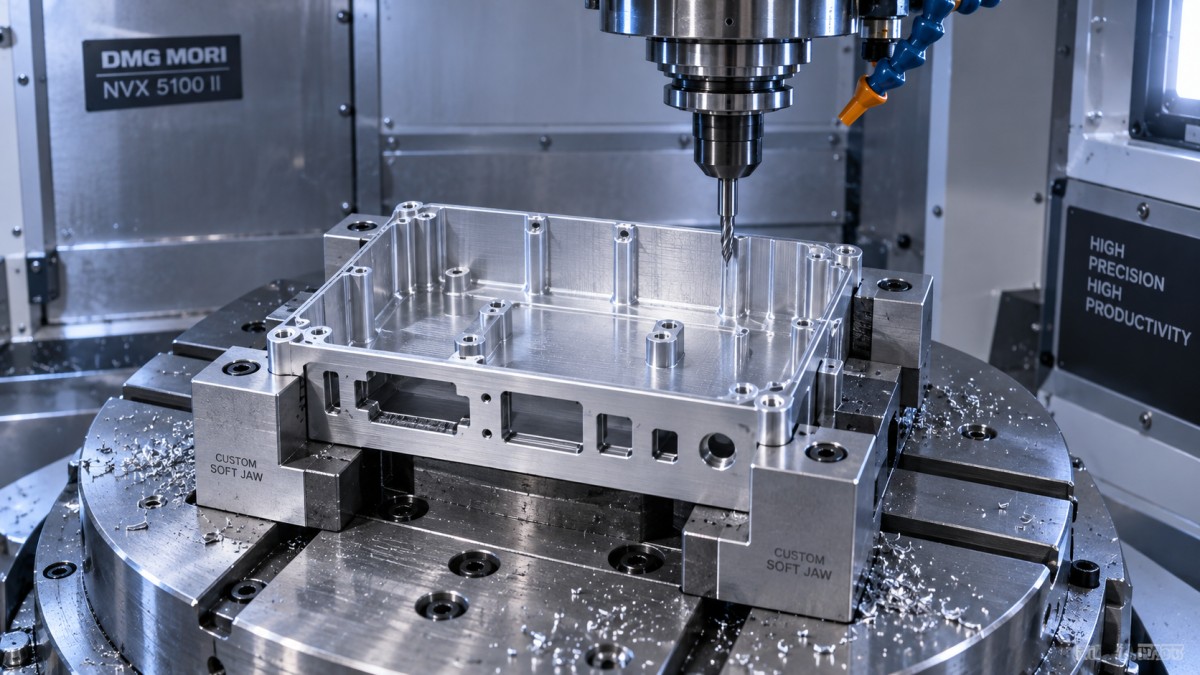
For roughing, low radial engagement toolpaths can limit force peaks, but they still require sensible axial depth, corner control, and chip evacuation. For finishing, a short, sharp cutter with consistent allowance may be more valuable than the highest possible material removal rate.
A very light finishing pass is not automatically a gentle finishing pass. If the effective chip thickness becomes too small for the cutting edge, rubbing can replace shearing. The result may be heat, poor finish, and unpredictable deflection. Establish finishing allowance from the tool geometry, material, and observed behavior—not from a blanket instruction to “leave almost nothing.”
Likewise, repeated spring passes should not be treated as a default solution. They may remove material left by deflection, but can also rub or create inconsistent results as the wall relaxes. If extra passes are required routinely, review support, tool reach, allowance, and cutting parameters.
Workholding and chip control belong in the tooling decision
A cutter evaluation conducted in an unrealistic fixture can produce a misleading winner. Support should sit close to vulnerable features without distorting them. Soft jaws, dedicated nests, internal supports, or sacrificial backing may help, depending on access and production requirements.
Vacuum workholding can be useful for some geometries, but holding force, sealing area, leakage, and local support need verification. Increased mechanical clamping pressure is not a universal remedy either: a housing can be machined accurately in its distorted state and spring back after release.
Coolant delivery should support the actual cut. In a deep pocket, flood coolant may fail to clear chips at the cutting edge. Air, minimum-quantity lubrication, or through-tool delivery can be appropriate in some applications, subject to material safety and machine capability. Evaluate chip removal throughout the pocket, not only at its entrance.
Connector openings and ventilation slots deserve separate burr trials. Exit conditions, edge wear, toolpath direction, and backing support all influence burr formation. A dedicated chamfering or deburring tool may be preferable to aggressive manual cleanup that risks altering a delicate edge.
How to evaluate electronics manufacturing tools for machining
A useful trial asks whether the tool can produce acceptable housings consistently—not whether it can make one attractive sample. Test candidates on representative geometry, with comparable holders, measured runout, controlled stock allowance, and documented coolant conditions.
Use the intended production machine where possible. Spindle speed capability alone says little about thin-wall performance. Axis behavior, spindle condition, thermal stability, and the tool-holder-fixture assembly all influence the result. Multi-axis access may shorten tool reach, but it also introduces additional positioning and collision considerations.
Record outcomes that reveal both quality and process stability:
- Released-part dimensions: wall profile, flatness, and interface location after unclamping, with temperature and measurement conditions controlled.
- Surface condition: measured roughness where specified, plus visible waviness and chatter.
- Edge quality: burr location, severity, and the effort required for removal.
- Wear progression: dimensional drift, edge damage, and finish changes across successive parts.
- Total production burden: cycle time, tool changes, deburring, inspection, rework, and scrap.
Change one major variable at a time during initial trials. Once a stable combination emerges, test reasonable variation in stock, tool wear, and setup repeatability. A process that succeeds only with a fresh edge and perfect conditions is not ready for unattended production.
Choose the process window, not the lowest cutter price
For technical evaluators, the strongest tooling proposal explains its limits as clearly as its benefits. Ask suppliers for alloy-specific geometry recommendations, permissible engagement, reach constraints, holder requirements, and observable wear criteria. Generic claims of suitability for “electronics machining” are not enough.
The final choice may involve separate roughing, semifinishing, wall-finishing, and edge-finishing tools. That adds inventory, but can reduce the much larger cost of unstable dimensions and manual correction. Compare cost per accepted housing rather than purchase price per cutter.
The best machining tools for thin-wall electronics housings are those that work within a verified combination of material, geometry, machine capability, support, and cutting strategy. Select for low and predictable forces, then prove dimensional stability after release. That is what turns a promising tooling trial into a production decision engineers can trust.
PREVIOUS ARTICLE
NEXT ARTICLE
Recommended for You
![]() Mitsubishi Electric Announces Physical AI System Linking Humanoid Robots and CNC MachinesMachine Tool Industry Editorial Team
 Precision Machining for Defense: Supplier Quality and Traceability ChecksManufacturing Market Research Center
![]() Nidec Machine Tool Launches MVR-5X Five-Axis Gantry MachineMachine Tool Industry Editorial Team
 Choosing a Precision Disc Parts Manufacturer in China: Tolerances and Quality ChecksManufacturing Market Research Center
![]() Siemens Executive Says AI Could Raise Factory Automation to 80%Manufacturing Market Research Center
 Choosing Automated Machine Tools for High-Mix, Low-Volume ProductionMachine Tool Industry Editorial Team


Aris Katos
Future of Carbide Coatings
15+ years in precision manufacturing systems. Specialized in high-speed milling and aerospace grade alloy processing.
▶
Choosing machining tools for thin-wall electronics housingsCNC Machining Technology Center▶
Which Metals Are Hardest to Machine With Standard Tools?CNC Machining Technology Center▶
How to Choose Cutting Tools for High-Speed Machining of Steel, Aluminum, and TitaniumCNC Machining Technology Center▶
How to Choose a CNC Tooling System for Titanium Machining by Tool Life and StabilityCNC Machining Technology Center▶
Cutting Tools Selection Guide: How Tool Material, Coating, and Geometry Affect PerformanceCNC Machining Technology Center
▶
Mastering 5-Axis Workholding Strategies
Join our technical panel on Nov 15th to learn about reducing vibrations in thin-wall components.

Providing you with integrated sanding solutions
Before-sales and after-sales services
Comprehensive technical support