• Global CNC market projected to reach $128B by 2028 • New EU trade regulations for precision tooling components • Aerospace deman
NYSE: CNC +1.2%LME: STEEL -0.4%

Common Burr, Surface, and Accuracy Issues in CNC Manufacturing for Electronics
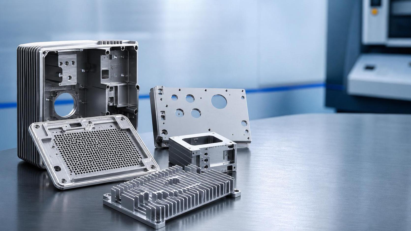
Why small defects become major problems in electronics machining
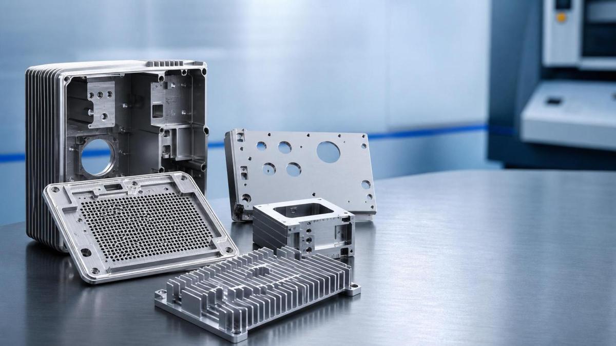
In CNC manufacturing for electronics, quality failures rarely start as dramatic errors. They usually begin with a fine burr, a rough edge, or a slight dimensional drift.
Those details matter because electronic parts often fit into dense assemblies. A tiny mismatch can affect shielding, connector seating, thermal contact, or automated installation stability.
This is why CNC manufacturing for electronics demands a different mindset from general structural machining. Tolerance, finish, and edge condition must be judged in the context of end use.
Across global precision manufacturing, machine tools are moving toward higher automation and digital integration. That shift helps, but it does not remove the need for process judgment on the shop floor.
A part for a phone housing, a heat sink, and a sensor bracket may all use similar CNC equipment. Their quality risks are still very different.
Actual production conditions change what matters most
The main issues in CNC manufacturing for electronics are usually burrs, surface inconsistency, and accuracy deviation. Yet the causes are not identical across applications.
Thin-wall aluminum enclosures often react badly to clamping force and heat. Connector blocks may be more sensitive to hole position and edge break. Copper parts raise another set of challenges.
In practical use, the better approach is to start with function. Ask how the part will be assembled, contacted, coated, tested, and handled downstream.
That is also why advanced machine tool clusters in China, Germany, Japan, and South Korea continue to refine tooling, fixturing, and automation together, not separately.
When burrs are the first hidden failure point
Burrs seem minor until they interfere with insertion, insulation spacing, or sealing. In electronics, even a light residual edge can scratch coated surfaces or disrupt connector fit.
This problem appears often in slot milling, drilled micro holes, and contour cutting on thin sections. Tool wear, unstable chip evacuation, and excessive feed at exit points are common triggers.
More common than expected is the mismatch between cutting strategy and material behavior. Aluminum may smear, copper may drag, and engineering plastics may deform instead of cutting cleanly.
Surface finish issues are not only cosmetic
Poor finish in CNC manufacturing for electronics is often treated as a visual defect. In reality, it can influence thermal transfer, adhesive bonding, coating consistency, and contamination control.
A rough cavity on a heat dissipation part may trap debris. A chatter mark on a shielding cover may affect contact quality. Visible tool lines can also complicate anodizing results.
The important judgment is whether the surface serves appearance, contact, or function. Each one requires a different finishing target and inspection method.
Accuracy problems often come from accumulation, not one dimension
Electronics parts may pass single-dimension inspection and still fail assembly. The reason is often positional accumulation across holes, pockets, datum shifts, and secondary operations.
This is especially common on multi-feature plates, camera modules, battery frames, and compact mounting structures. Small errors stack quickly when spacing is tight.
In CNC manufacturing for electronics, process capability matters more than isolated measurement. Stable repeatability is what protects yield in volume production.
Different electronics parts call for different control priorities
Not every electronic component should be controlled in the same way. The table below shows why the same defect may carry very different risk in different machining contexts.
This kind of comparison is useful because CNC manufacturing for electronics is rarely limited by machine capability alone. The limiting factor is often process matching.
What usually works better on the shop floor
For burr control, tool life should be monitored by edge quality, not only by cutting time. A tool may still cut dimensions correctly while already producing unstable burr formation.
For surface consistency, finishing passes should reflect the final function. A cosmetic outer face and a thermal contact face should not automatically share the same strategy.
For accuracy, datum design deserves more attention than many teams give it. Secondary setups often introduce more variation than spindle accuracy itself.
- Use fixture support that matches thin, flexible, or heat-sensitive geometry.
- Separate roughing and finishing where material stress release is likely.
- Match coolant delivery to chip evacuation in slots, pockets, and micro features.
- Check post-process cleaning where burr fragments or residue may remain trapped.
- Link inspection points to assembly risk, not only to drawing convenience.
In highly automated production lines, these controls are even more important. Automation amplifies both good process design and bad assumptions.
Where teams often misread the problem
One frequent mistake is treating similar electronics parts as identical. Two aluminum brackets may look alike, while one needs cosmetic quality and the other needs electrical contact stability.
Another mistake is focusing only on machine parameters. In CNC manufacturing for electronics, fixture pressure, tool path exit direction, and cleaning method can be just as decisive.
Some operations also underestimate downstream effects. A small burr left after milling may not fail inspection, but it can break off during assembly and create contamination risk.
There is also a cost misunderstanding. Lower machining cost per piece may look attractive, yet rework, sorting, and assembly stoppage can erase that advantage quickly.
A more reliable way to judge process fit
Before locking the process, it helps to confirm several points in sequence rather than in isolation.
- Which surfaces are functional, visible, or contact-critical.
- Which features are most sensitive to burrs after assembly.
- Whether tolerance risk comes from one feature or accumulated positioning.
- How coating, plating, or bonding may change acceptance limits.
- Whether production volume requires manual correction or true process stability.
Turning quality lessons into a practical next step
CNC manufacturing for electronics works best when quality targets follow real application conditions. Burrs, surface finish, and accuracy should be judged by assembly behavior and functional performance.
A useful next step is to sort parts by use case, then compare fixture method, material response, finish expectation, and tolerance stack risk for each group.
From there, build a process checklist around edge control, critical surfaces, datums, cleaning, and inspection frequency. That approach is more dependable than reacting only after scrap appears.
As global precision manufacturing keeps advancing through smarter machine tools and integrated production systems, the strongest results still come from matching the process to the part’s actual job.
Recommended for You
 Industrial Machining: Selecting Processes for Tight-Tolerance Metal PartsCNC Machining Technology Center
 Manufacturing Technology Trends That Improve Throughput and Quality ControlManufacturing Market Research Center
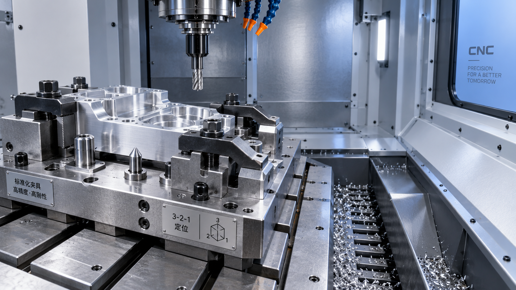
 How to Design Cost-Effective Fixtures That Maintain Cycle Time in Mass ProductionCNC Machining Technology Center
 Is Learning CNC Programming Worth It for Shop Owners Seeking Higher Margins?CNC Machining Technology Center
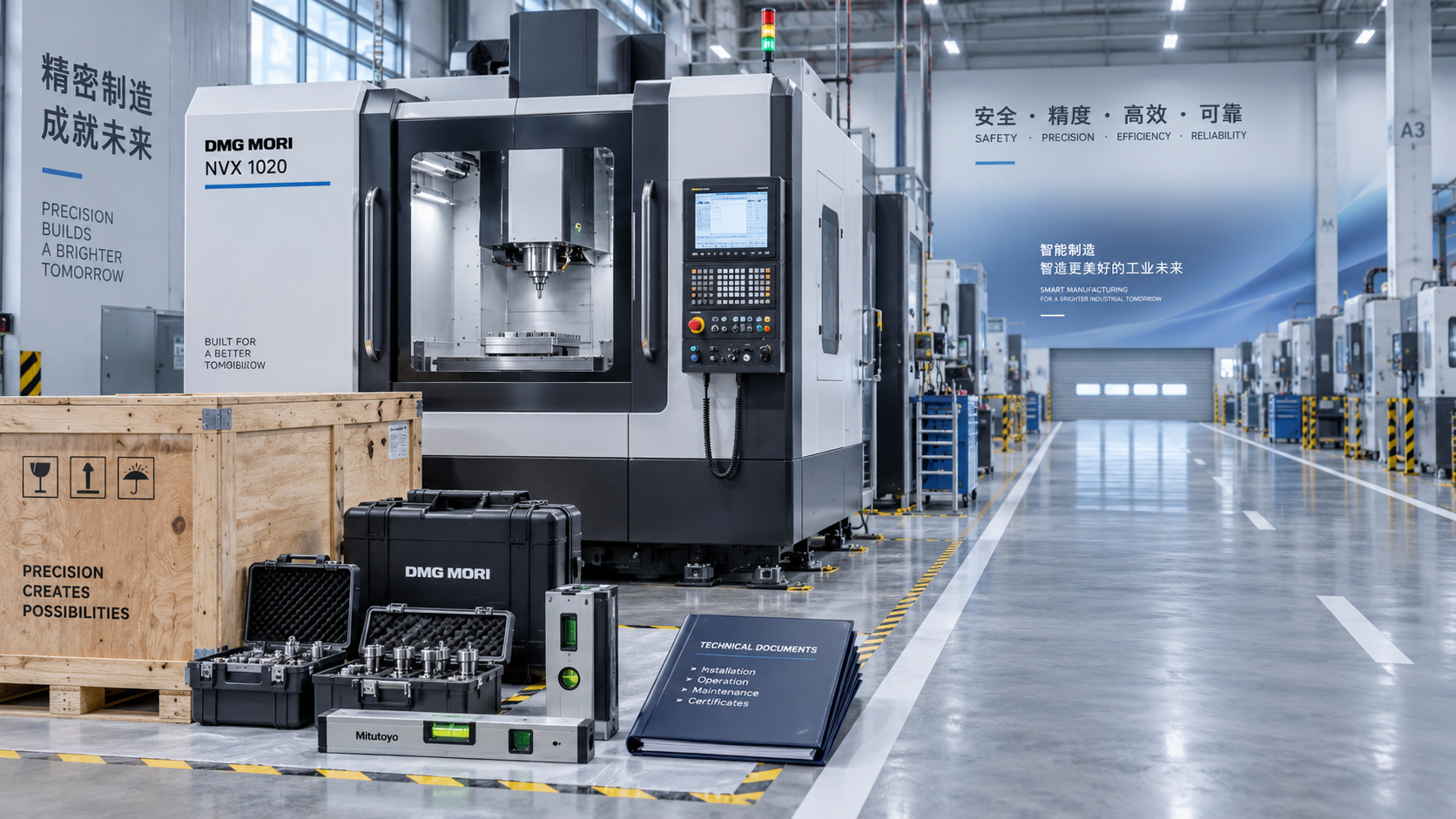
 CNC Machine Arrival Inspection: Check Shipping Damage, Accuracy, Safety, and DocumentsCNC Machining Technology Center
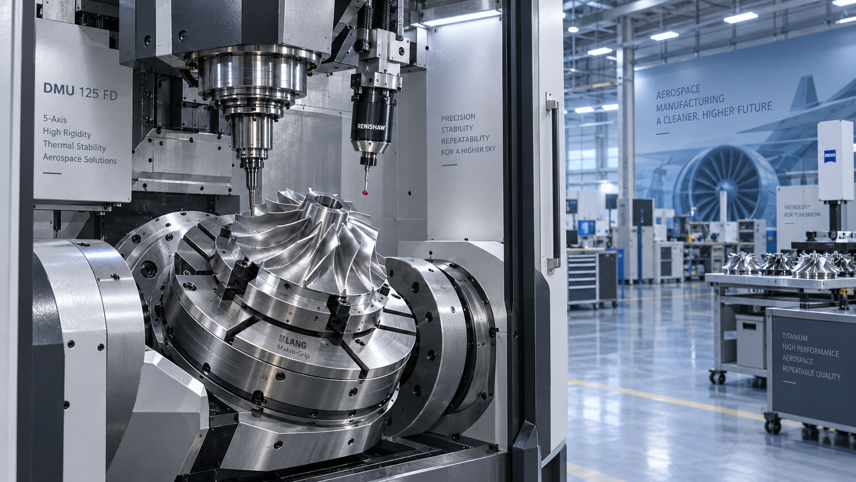
 How to Select a Machine Tool for Aerospace Parts with Tight Tolerances?Machine Tool Industry Editorial Team

Aris Katos
Future of Carbide Coatings
15+ years in precision manufacturing systems. Specialized in high-speed milling and aerospace grade alloy processing.
▶
CNC Machine Arrival Inspection: Check Shipping Damage, Accuracy, Safety, and DocumentsCNC Machining Technology Center▶
What Should You Check When a CNC Machine Arrives at Your Factory?CNC Machining Technology Center▶
What Safety Checks Are Required for CNC Cutting Operations?CNC Machining Technology Center▶
What Are Machine Tools? Common Types, Functions, and Typical Shop ApplicationsCNC Machining Technology Center▶
CNC Industrial Machines Maintenance Checklist: How to Reduce Downtime and Tool WearCNC Machining Technology Center
Mastering 5-Axis Workholding Strategies
Join our technical panel on Nov 15th to learn about reducing vibrations in thin-wall components.

Providing you with integrated sanding solutions
Before-sales and after-sales services
Comprehensive technical support