• Global CNC market projected to reach $128B by 2028 • New EU trade regulations for precision tooling components • Aerospace deman
NYSE: CNC +1.2%LME: STEEL -0.4%

CNC Precision: Which Tolerances, Materials, and Processes Fit Your Part?
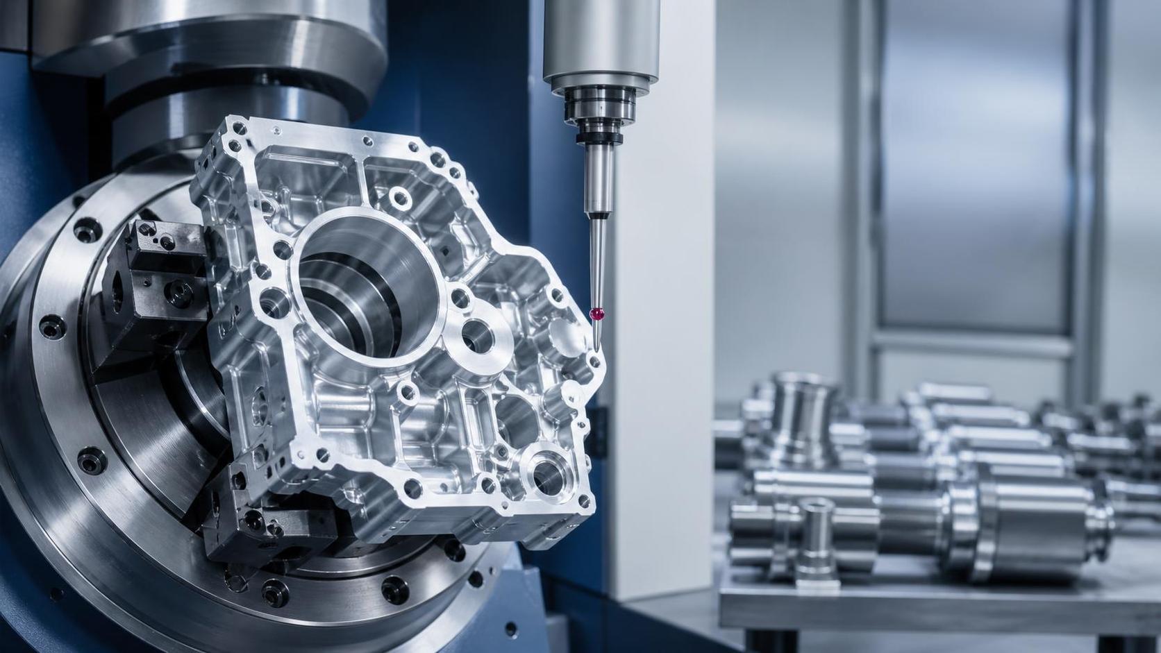
A part is not “precision CNC” simply because its drawing shows a tight number. The practical question is whether the specified tolerance, material, geometry, surface condition, and inspection method can work together at an acceptable cost and production risk. A tolerance that is reasonable on a short steel bore may be expensive or unstable on a thin-walled aluminum housing, a long plastic component, or a part that changes after heat treatment.
For technical evaluation, the right CNC precision strategy starts with function. Identify the features that locate, seal, rotate, carry load, mate with another part, or control a critical clearance. Apply the highest accuracy only where that function requires it. Then select the material and machining process that can repeatedly achieve it.
Start with functional tolerances, not the smallest possible number
Every dimension does not need the same level of control. A common source of unnecessary machining cost is applying a tight general tolerance to an entire drawing when only a few interfaces are critical. This increases setup time, inspection effort, tool wear, scrap risk, and sometimes lead time without improving part performance.
Separate dimensions into three groups:
- Critical features: bearing seats, locating bores, sealing faces, precision threads, gear interfaces, datum surfaces, and mating profiles. These usually need clearly defined dimensional, geometric, and surface requirements.
- Controlled features: dimensions affecting assembly clearance, wall thickness, stiffness, or appearance. These need sensible limits but may not require high-precision finishing.
- Non-critical features: external contours, clearance pockets, cosmetic edges, and dimensions with no direct functional role. Broader tolerances often improve manufacturability substantially.
A dimensional tolerance alone does not fully define precision. A shaft diameter may be within size limits but still fail in service because it is tapered, out of round, bent, or poorly finished. Likewise, two accurately machined surfaces may not assemble correctly if their positional relationship is uncontrolled. Where assembly function depends on orientation or location, geometric tolerances such as position, flatness, perpendicularity, concentricity, or runout are often more meaningful than reducing every linear tolerance.
The drawing should also establish usable datums. If the supplier and inspector cannot identify the same functional reference surfaces, the reported measurements may look acceptable while the assembly still fails. Precision depends on a shared measurement strategy, not only on a capable machine.
What makes a tolerance difficult in real machining
The difficulty of a tolerance depends on the feature, not merely the value shown on the print. Internal bores are generally harder to control than external diameters because tool access, chip removal, and tool deflection are less favorable. Deep cavities, thin ribs, long slender shafts, interrupted cuts, and features placed far from the workholding point all introduce additional variation.
Part size matters as well. A tight requirement over a short distance can be achievable with a stable setup, while the same requirement across a long structure may be affected by machine geometry, clamping distortion, temperature change, and material stress relief. Thin-wall parts create another problem: a component can measure correctly while clamped, then move after release.
Surface finish should be specified for a functional reason. A sealing face, sliding guide, optical-contact surface, or bearing interface may need a defined finish. A non-contact exterior surface usually does not benefit from a demanding finish requirement. Finer finishes can require extra passes, specialized tooling, slower cutting conditions, or secondary processes, so they should not be used as a general proxy for quality.
Before releasing a request for quotation, review whether the tolerance applies before or after finishing, plating, anodizing, coating, or heat treatment. Those operations can change dimensions, alter surface condition, or introduce distortion. A bore intended for a press-fit component may need to be machined differently depending on whether the final size is required before or after surface treatment.
Material choice changes the CNC precision plan
Materials do not behave the same under cutting forces, heat, clamping pressure, or environmental change. Selecting a material solely by strength, weight, or cost can create avoidable precision problems later in the process.
For polymer parts, the question is often not whether the CNC machine can cut the dimension, but whether the dimension remains stable during use. A plastic part that fits at room temperature may behave differently in a warm enclosure, humid environment, or sustained clamping condition. Where long-term stability is critical, material behavior in service should be considered alongside machining capability.
Material stock condition also deserves attention. Residual stress in plate, bar, or forged stock can appear after roughing, especially when a large amount of material is removed from one side. For distortion-sensitive components, a staged roughing and finishing approach may be more reliable than machining the final geometry in a single operation.
Match the CNC process to geometry and production demand
Process selection should follow the dominant geometry of the part. A machining center can make many shapes, but it is not always the most efficient or stable route for every feature.
Turning for rotational features
CNC turning is usually the natural choice for shafts, sleeves, discs, rings, threaded diameters, and concentric bore-and-diameter relationships. It provides a direct way to control roundness, runout, and coaxial features when the part can be referenced from a reliable axis. Live tooling can add cross holes, flats, or milled features, reducing transfers for moderately complex turned parts.
Turning becomes less attractive when the component is mainly prismatic, requires extensive off-axis work, or has complex surfaces that cannot be reached efficiently from the spindle orientation.
Three-axis milling for accessible prismatic parts
Three-axis machining is appropriate for many plates, housings, brackets, manifolds, fixtures, and structural parts where the required features can be reached through a limited number of setups. It is often economical for straightforward pockets, drilled patterns, faces, and exterior profiles.
The main limitation is re-clamping. Every setup transfer can add alignment error and inspection complexity. If positional relationships between multiple faces are critical, reducing the number of setups may be more valuable than selecting a machine with a higher headline accuracy.
Four- and five-axis machining for access and setup reduction
Multi-axis machining is useful when a part has compound angles, multiple precision faces, impeller-like forms, deep side features, or relationships that are difficult to preserve through repeated clamping. The advantage is not automatically tighter tolerance. Its practical value is often better feature access and fewer datum transfers.
A five-axis process should be justified by geometry, required relationships, volume, and setup risk. For a simple block with features on two faces, it may add programming and fixturing complexity without meaningful benefit. For a complex aerospace-style bracket or a part with angled bores that must relate closely to a central datum, it can simplify the process considerably.
Grinding, honing, and EDM for features milling or turning cannot finish reliably
Conventional CNC cutting is not the only precision route. Grinding may be appropriate for hardened external diameters, flat precision surfaces, or features requiring a controlled final condition after heat treatment. Honing can be useful where bore geometry and surface behavior are especially important. Electrical discharge machining is often considered for conductive materials with sharp internal corners, narrow slots, delicate profiles, or hard materials that are difficult to cut conventionally.
These processes should be chosen because they solve a specific feature problem, not because they sound more precise. They add process stages, inspection requirements, and handling risk. A part can become less economical and less predictable if secondary finishing is used where improved workholding or a better feature design would have been enough.
Design details that protect repeatability
Repeatability is what turns a successful prototype into a reliable production part. It depends on workholding, tool reach, cutting load, datum control, and inspection access. Features that are easy to model may still be difficult to hold consistently.
- Avoid deep, narrow pockets when the function allows a wider opening or shallower depth. Long tools deflect more easily and can leave tapered walls or inconsistent corners.
- Use internal corner radii that match realistic cutter sizes. A sharp internal corner typically requires a secondary operation, EDM, or a design change.
- Provide enough material around bores and threads. Very thin local walls may deform during machining, fastening, or assembly.
- Place critical features so they can be reached from a stable datum. A precision bore on a flexible extension is more difficult to control than the same bore near the clamping area.
- Define deburring expectations where edge condition affects assembly, sealing, safety, or coating. “Remove sharp edges” alone may not communicate the intended result for a critical interface.
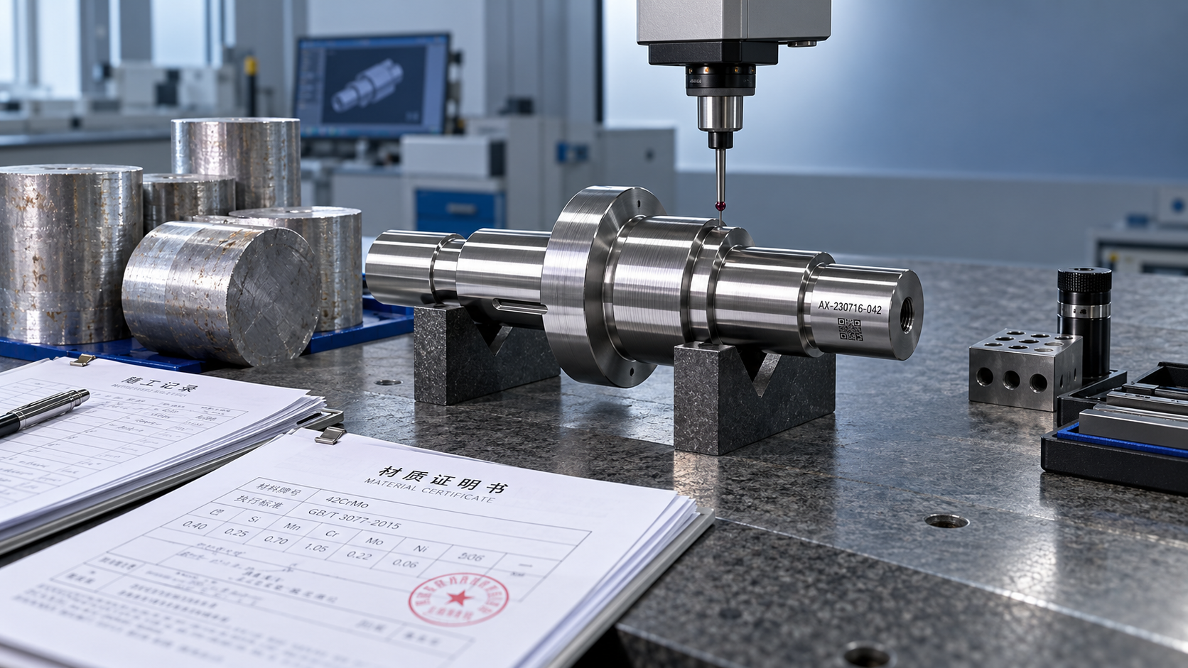
Inspection must be feasible at the same level as the requirement. A critical bore may be checked with a functional gauge, a precision measuring instrument, or a coordinate measurement method depending on the feature and production stage. Complex freeform surfaces may require digital comparison against the CAD model. If a requirement cannot be measured consistently, it cannot be managed consistently in production.
A practical evaluation sequence before committing to a supplier or process
Technical evaluators get more useful quotations and fewer late-stage changes by reviewing the part in the order the manufacturing process will encounter it:
- Define the function of each critical feature. Identify fits, sealing surfaces, motion interfaces, load paths, electrical contacts, and cosmetic areas.
- Set datums around assembly logic. Reference the surfaces or axes that actually locate the part in its next operation or final assembly.
- Assign dimensional and geometric controls selectively. Tighten only the features where variation creates a functional failure.
- Check material behavior through the full process. Include roughing, finishing, heat treatment, coating, cleaning, and service environment where relevant.
- Select the machining route based on feature access and setup count. Choose turning, milling, multi-axis work, or secondary finishing according to the geometry rather than the broad label of “high precision.”
- Agree on inspection for critical characteristics. The production plan should state what is measured, from which datums, and at what stage.
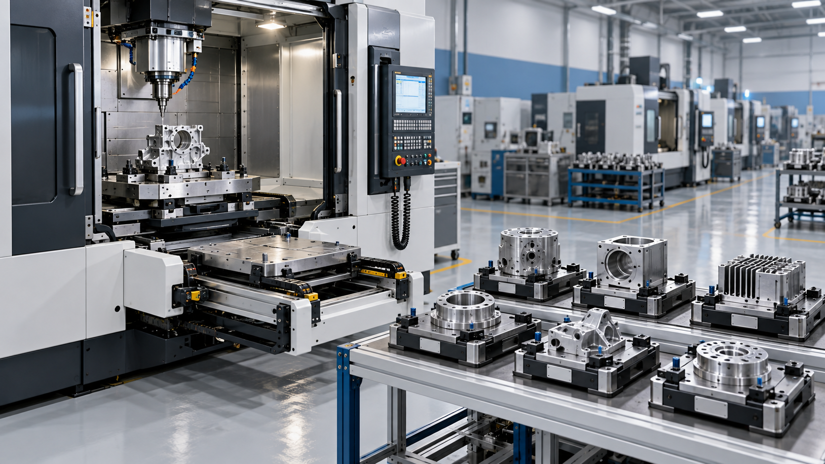
Production volume changes the decision but does not replace this sequence. A low-volume prototype may tolerate more manual setup and inspection. A repeated production program benefits from dedicated fixtures, stable tooling, probe routines, automated loading, or an integrated manufacturing cell when those investments reduce variation and cycle-to-cycle handling. The part requirements still determine whether that automation is useful.
Questions that reveal an under-specified CNC precision request
When a quotation appears unexpectedly high, or suppliers propose different processes for the same drawing, the issue is often incomplete manufacturing intent rather than a lack of machining capability. Clarify these points before comparing prices:
- Which dimensions are functional after all finishing operations?
- Are form and position requirements as important as final size?
- Does the part need to maintain its fit across temperature changes, humidity, load, or corrosion exposure?
- Can a critical feature be inspected without disassembling or damaging the part?
- Is the expected quantity a prototype batch, repeat order, or long-running production program?
- Would a small design change reduce setups, tool reach, special fixturing, or secondary operations?
The strongest CNC precision decisions do not begin by asking for the tightest tolerance available. They begin by identifying the part features that control product function, then building a material, process, workholding, and inspection plan around those features. That approach protects assembly performance while avoiding precision requirements that consume cost without creating value.
Recommended for You
![]() Mitsubishi Electric Announces Physical AI System Linking Humanoid Robots and CNC MachinesMachine Tool Industry Editorial Team
Mitsubishi Electric Announces Physical AI System Linking Humanoid Robots and CNC MachinesMachine Tool Industry Editorial Team Precision Machining for Defense: Supplier Quality and Traceability ChecksManufacturing Market Research Center
![]() Nidec Machine Tool Launches MVR-5X Five-Axis Gantry MachineMachine Tool Industry Editorial Team
Nidec Machine Tool Launches MVR-5X Five-Axis Gantry MachineMachine Tool Industry Editorial Team Choosing a Precision Disc Parts Manufacturer in China: Tolerances and Quality ChecksManufacturing Market Research Center
![]() Siemens Executive Says AI Could Raise Factory Automation to 80%Manufacturing Market Research Center
Siemens Executive Says AI Could Raise Factory Automation to 80%Manufacturing Market Research Center Choosing Automated Machine Tools for High-Mix, Low-Volume ProductionMachine Tool Industry Editorial Team


Aris Katos
Future of Carbide Coatings
15+ years in precision manufacturing systems. Specialized in high-speed milling and aerospace grade alloy processing.
▶
How thermal drift affects accuracy in high-precision manufacturingCNC Machining Technology Center▶
Industrial Machining: Selecting Processes for Tight-Tolerance Metal PartsCNC Machining Technology Center▶
How Does Precision Machining Differ From Standard Machining?CNC Machining Technology Center▶
CNC Precision: Which Tolerances, Materials, and Processes Fit Your Part?CNC Machining Technology Center▶
How to Choose Metal Machining Processes for Tight Tolerances and Production VolumeCNC Machining Technology Center
▶
Mastering 5-Axis Workholding Strategies
Join our technical panel on Nov 15th to learn about reducing vibrations in thin-wall components.

Providing you with integrated sanding solutions
Before-sales and after-sales services
Comprehensive technical support