• Global CNC market projected to reach $128B by 2028 • New EU trade regulations for precision tooling components • Aerospace deman
NYSE: CNC +1.2%LME: STEEL -0.4%

Why Choose a 5 Axis Machining center for aerospace parts?
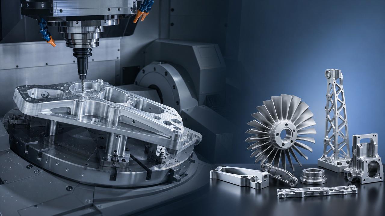
For technical evaluation in aerospace manufacturing, equipment selection directly affects accuracy, stability, and production efficiency.
A 5 Axis Machining center for aerospace parts supports complex geometries, tight tolerances, and fewer setups across demanding production environments.
As aircraft structures become lighter and more integrated, multi-axis capability helps improve repeatability, surface quality, and scalable precision machining.
When Aerospace Part Geometry Makes 5-Axis Capability Necessary
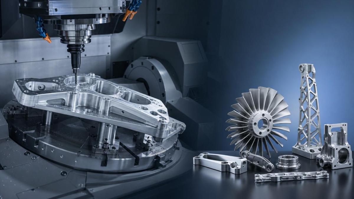
Aerospace components often combine thin walls, deep pockets, curved surfaces, and difficult access angles.
A 5 Axis Machining center for aerospace parts becomes valuable when these features cannot be reached efficiently with three-axis machining.
The key scenario is not only complexity. It is the relationship between geometry, tolerance, setup count, and cutting stability.
With simultaneous five-axis movement, tools can approach surfaces from optimal angles while maintaining shorter tool overhang.
This reduces chatter, improves surface finish, and protects dimensional accuracy on high-value aerospace parts.
The strongest application value appears when a part needs multiple angled features in one clamping.
In these cases, a 5 Axis Machining center for aerospace parts reduces cumulative positioning errors caused by repeated repositioning.
Scenario Background: Different Aerospace Parts Require Different Judgments
Not every aerospace component requires the same machining strategy, even when the material looks similar.
Structural frames, turbine parts, housings, brackets, and mold tooling each create different demands on rigidity and control.
A 5 Axis Machining center for aerospace parts should be evaluated through part families, not isolated specifications.
The correct decision depends on feature accessibility, surface requirements, batch size, inspection burden, and material behavior.
For titanium and nickel alloys, the machine must manage cutting force, heat, and tool wear under stable conditions.
For aluminum aerospace structures, speed, chip evacuation, and dynamic accuracy often become more important.
For composite-related tooling, surface continuity and smooth tool orientation may dominate the evaluation.
Structural Components: Reducing Setups and Protecting Datum Accuracy
Aircraft ribs, bulkheads, spars, and frame parts usually include pockets, bosses, ribs, and angled holes.
These parts are often large, lightweight, and sensitive to deformation during machining.
A 5 Axis Machining center for aerospace parts helps machine multiple faces from one setup.
This reduces datum transfer errors and keeps relationships between holes, pockets, and profiles more consistent.
For thin-wall structures, tool angle control also reduces cutting pressure and vibration.
The practical judgment point is whether the process suffers from repeated clamping, long tools, or unstable wall finishing.
If these problems appear frequently, five-axis machining can improve both quality and process reliability.
Turbine and Engine Parts: Managing Curved Surfaces and Hard Materials
Engine components often require continuous surface quality, precise profiles, and reliable machining of heat-resistant alloys.
Typical parts include blades, blisks, casings, impellers, and complex transition surfaces.
A 5 Axis Machining center for aerospace parts enables smoother tool paths on sculptured surfaces.
By maintaining proper tool contact, the process can reduce scallop marks and improve aerodynamic surface integrity.
For nickel-based alloys, rigidity, thermal stability, and spindle torque become critical selection factors.
Five-axis positioning alone is not enough if the machine cannot resist cutting loads.
The best fit appears when simultaneous motion, CAM strategy, cooling, and tool selection work as one system.
Precision Housings and Brackets: Improving Feature Alignment
Aerospace housings and brackets often include intersecting holes, angled ports, sealing surfaces, and tight positional tolerances.
In these scenarios, the main risk is feature misalignment caused by multiple setups.
A 5 Axis Machining center for aerospace parts can complete more features without moving the workpiece.
This makes it easier to maintain geometric relationships between critical faces, bores, and mounting points.
For low-volume, high-mix aerospace production, this flexibility has strong operational value.
The decision should consider whether fixture design has become too complex or inspection correction is too frequent.
When fixtures compensate for machine limitations, a five-axis solution may simplify the entire process route.
Different Aerospace Scenarios and Machining Requirements
This comparison shows why a 5 Axis Machining center for aerospace parts should match specific process bottlenecks.
The strongest business case appears when accuracy, setup reduction, and cycle stability improve together.
Selection Factors That Influence Scenario Fit
Machine configuration should be matched with part size, material, travel range, and required precision.
A 5 Axis Machining center for aerospace parts may use trunnion, swivel head, or gantry-style structures.
Small precision parts often benefit from compact rotary tables with strong positioning accuracy.
Large aircraft structures may require long-axis travel, high rigidity, and stable thermal compensation.
- Check whether the work envelope covers the real part and fixture combination.
- Evaluate rotary axis accuracy under actual cutting loads, not only catalog values.
- Confirm spindle speed, torque, and cooling for aluminum, titanium, or nickel alloys.
- Review CAM compatibility, post-processing reliability, and collision simulation capability.
- Assess probing, tool measurement, and in-process inspection for closed-loop control.
These points turn a machine comparison into a scenario-based production decision.
Process Stability: The Hidden Value Behind Five-Axis Machining
The value of a 5 Axis Machining center for aerospace parts is often measured by more than cycle time.
Stable processes reduce scrap risk, rework, manual adjustment, and inspection disputes.
Aerospace parts usually carry high material costs and strict traceability requirements.
When one rejected component causes major cost loss, process predictability becomes a decisive factor.
Five-axis machining helps by shortening tool length, improving access, and reducing handling between operations.
It also supports probing routines that verify critical features before the part leaves the machine.
This is especially important for low-volume aerospace programs where learning time is limited.
Common Misjudgments When Evaluating Aerospace Five-Axis Needs
One common mistake is treating five-axis machining as only a solution for complex shapes.
In reality, a 5 Axis Machining center for aerospace parts also solves alignment, access, and consistency challenges.
Another mistake is focusing only on machine travel while ignoring fixture clearance and tool reach.
A machine may appear large enough, yet still create collision limits during real five-axis motion.
Some evaluations also underestimate software, simulation, and operator skill requirements.
Without reliable CAM posts and collision control, five-axis capability cannot be safely converted into production value.
Tooling is another frequent blind spot, especially for titanium and nickel alloy machining.
The machine, tool, fixture, coolant, and program must be evaluated as one aerospace machining system.
Scenario-Based Recommendations for Practical Implementation
A practical selection process should begin with representative part families and real process pain points.
The goal is to identify where a 5 Axis Machining center for aerospace parts creates measurable improvement.
- Group parts by geometry, material, tolerance level, and expected batch volume.
- Map current setup counts, cycle times, inspection failures, and rework causes.
- Simulate five-axis tool paths using actual fixtures and cutting tools.
- Compare surface finish, datum stability, and tool life under test cuts.
- Build a return model based on scrap reduction, labor savings, and throughput gains.
This approach avoids buying capacity without understanding where it will be used.
It also helps define machine specifications that match aerospace manufacturing realities.
Why the Decision Matters for Modern Precision Manufacturing
The CNC machine tool industry is moving toward higher precision, automation, and digital integration.
Aerospace production reflects this transformation because parts demand accuracy, traceability, and efficient process control.
A 5 Axis Machining center for aerospace parts fits this trend by connecting machining flexibility with smart manufacturing needs.
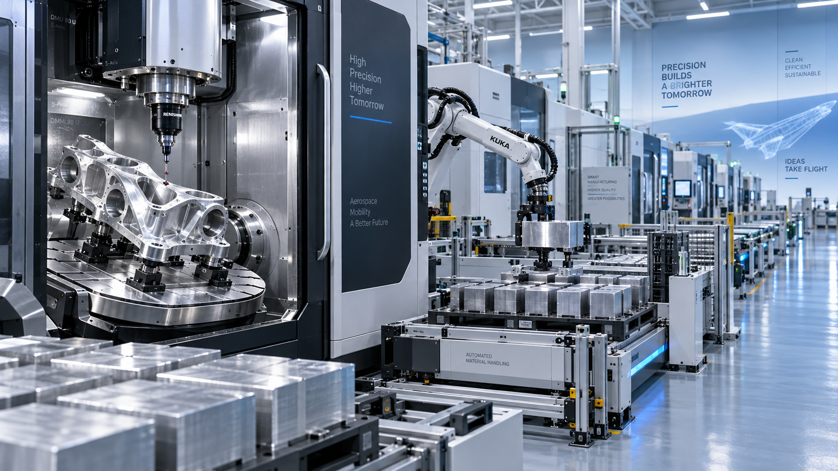
When integrated with probing, tool management, robotics, and production data systems, it supports more consistent output.
This is important for factories handling high-mix aerospace work and changing program requirements.
The equipment decision should therefore consider both current parts and future process expansion.
Action Guide: Turning Evaluation Into a Reliable Machining Plan
Start with the parts that create the highest quality risk, longest setup time, or most difficult inspection burden.
Then test whether a 5 Axis Machining center for aerospace parts improves the complete workflow.
The next step is to request application studies, cutting demonstrations, and process simulations using representative aerospace components.
Compare not only machining time, but also datum control, fixture simplification, tool life, and inspection stability.
A suitable 5 Axis Machining center for aerospace parts should make complex production more predictable, not simply more advanced.
When the scenario, machine configuration, tooling, and digital process are aligned, five-axis machining becomes a practical path to aerospace-grade precision.
PREVIOUS ARTICLE
Recommended for You
 How to Select a CNC Metal Lathe for Tight-Tolerance Shaft and Sleeve PartsCNC Machining Technology Center
 How to Select an Industrial Lathe for High-Volume Shaft ProductionMachine Tool Industry Editorial Team
 Selecting Machine Tools for Automotive Parts: Accuracy, Throughput, and AutomationMachine Tool Industry Editorial Team
 Industrial Machining: Selecting Processes for Tight-Tolerance Metal PartsCNC Machining Technology Center
 Manufacturing Technology Trends That Improve Throughput and Quality ControlManufacturing Market Research Center
 How to Design Cost-Effective Fixtures That Maintain Cycle Time in Mass ProductionCNC Machining Technology Center

Aris Katos
Future of Carbide Coatings
15+ years in precision manufacturing systems. Specialized in high-speed milling and aerospace grade alloy processing.
▶
Industrial Machining: Selecting Processes for Tight-Tolerance Metal PartsCNC Machining Technology Center▶
How Does Precision Machining Differ From Standard Machining?CNC Machining Technology Center▶
CNC Precision: Which Tolerances, Materials, and Processes Fit Your Part?CNC Machining Technology Center▶
How to Choose Metal Machining Processes for Tight Tolerances and Production VolumeCNC Machining Technology Center▶
Production Process Explained: Key Stages, Controls, and Quality CheckpointsCNC Machining Technology Center
Mastering 5-Axis Workholding Strategies
Join our technical panel on Nov 15th to learn about reducing vibrations in thin-wall components.

Providing you with integrated sanding solutions
Before-sales and after-sales services
Comprehensive technical support