• Global CNC market projected to reach $128B by 2028 • New EU trade regulations for precision tooling components • Aerospace deman
NYSE: CNC +1.2%LME: STEEL -0.4%

Industrial Robotics for Welding Applications: How to Plan a Stable Cell Layout
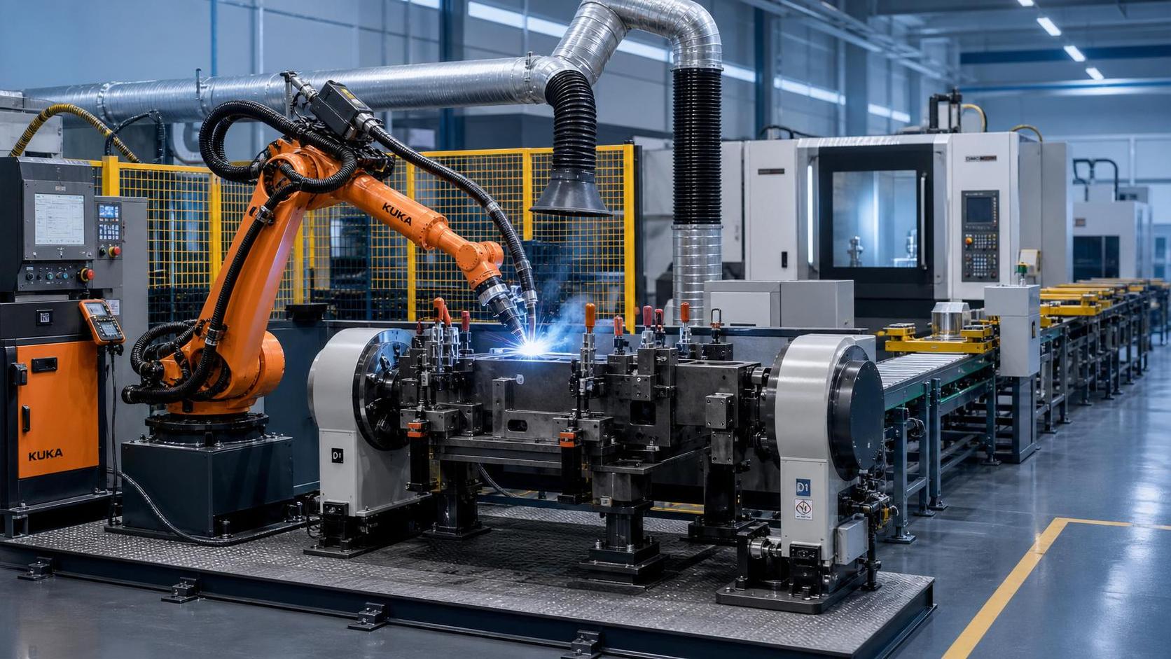
Industrial Robotics for Welding Applications: How to Plan a Stable Cell Layout
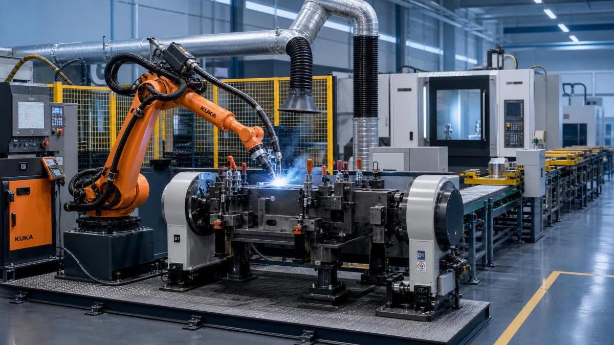
Industrial Robotics for Welding Applications are changing how manufacturers build repeatable, high-output welding operations.
A stable cell layout is not just an engineering detail. It directly affects uptime, weld quality, labor efficiency, and expansion costs.
That matters even more in sectors tied to CNC machining, precision parts, automotive systems, aerospace structures, and energy equipment.
When welded parts feed machining centers or automated assembly lines, layout instability quickly becomes a production bottleneck.
In practice, Industrial Robotics for Welding Applications work best when the full cell is planned as a system, not as a robot plus a fixture.
This includes part flow, torch access, operator movement, maintenance clearance, cable routing, fume extraction, and future model changes.
The goal is simple: create a welding cell that stays stable under real production conditions, not only during factory acceptance testing.
Why layout stability matters more than robot speed
Many investment decisions start with robot payload, reach, and cycle time. Those metrics matter, but layout stability usually decides long-term performance.
An unstable cell creates small losses everywhere. Position errors increase rework. Poor access slows maintenance. Tight clearance raises collision risk.
Over time, those losses become expensive, especially in high-mix production or multi-shift operations.
Industrial Robotics for Welding Applications depend on repeatable conditions. Robot programming cannot fully compensate for weak fixturing or inconsistent part loading.
A stable layout also supports predictable quality control. That is important when welded assemblies move to CNC machining with tight downstream tolerances.
From a business standpoint, stable layout planning lowers ramp-up risk and makes automation ROI easier to defend.
Start with the welding process, not the floor plan
The best cell layouts begin with process requirements. That means joint type, weld sequence, heat input, part variation, and target takt time.
Different Industrial Robotics for Welding Applications need different layouts. Arc welding, spot welding, laser welding, and hybrid cells do not behave the same.
For example, large fabricated frames need wide robot travel and rigid positioning. Small precision parts need shorter motion paths and stronger fixture repeatability.
This is where manufacturers often underestimate part family analysis. If product mix changes often, the cell must absorb variation without frequent rebuilds.
A practical planning sequence usually includes:
- Define the weld process, materials, part size range, and required quality standard.
- Map the production flow before and after welding.
- Confirm fixture strategy, loading method, and part orientation.
- Validate robot reach, torch angles, and service access.
- Reserve space for extraction, safety, and future equipment additions.
That order helps Industrial Robotics for Welding Applications fit real manufacturing needs instead of forcing the process to fit the robot.
Core elements of a stable welding cell layout
A stable layout is built on several connected design choices. Weakness in one area often creates hidden stress elsewhere in the cell.
1. Robot base position
Place the robot where most weld points sit inside the strongest working envelope. Avoid layouts that depend on extreme reach.
Extreme reach reduces stiffness, slows movement, and increases cable stress. It also makes future part changes harder to absorb.
2. Fixture and positioner design
Fixtures must locate parts consistently and resist thermal distortion. For many Industrial Robotics for Welding Applications, the positioner matters as much as the robot.
A well-chosen headstock-tailstock or turntable can reduce robot motion, improve torch angle control, and shorten cycle time.
3. Material flow
Inbound and outbound paths should stay clear, simple, and visible. Forklifts, AGVs, pallets, and manual carts need separated movement zones.
When traffic crosses operator zones, small delays and safety concerns appear quickly.
4. Maintenance access
Leave room for torch cleaning, cable replacement, sensor checks, and positioner service. A compact layout is not always an efficient one.
5. Utilities and environment
Power, shielding gas, compressed air, wire feed, cooling, and extraction should support stable operation without cluttering motion paths.
This becomes especially important in Industrial Robotics for Welding Applications integrated with CNC machine cells or digital production lines.
Common layout mistakes that reduce welding cell stability
Several planning errors appear again and again across automated welding projects. Most are avoidable with earlier cross-functional review.
- Choosing the robot before confirming part range and weld access.
- Using fixtures that prioritize low cost over repeatability.
- Ignoring cable wear and torch collision zones during offline layout design.
- Underestimating fume extraction impact on operator access and visibility.
- Leaving no room for quality inspection, rework handling, or consumable storage.
- Designing only for current parts, with no path for future product variants.
These issues often surface after installation, when fixes become expensive. That is why simulation alone is not enough.
For Industrial Robotics for Welding Applications, physical trial planning, maintenance input, and operator feedback still matter.
How to evaluate layout options before capital approval
Decision quality improves when layout options are compared through a simple scoring model rather than a purely visual review.
A practical evaluation table can align engineering, operations, and finance around the same risk picture.
This type of review is useful for Industrial Robotics for Welding Applications in precision manufacturing, where product changes are common.
It also creates a clearer record for supplier comparison and capital expenditure approval.
Planning for flexibility in real production conditions
A stable layout should not be rigid. It should handle variation without losing control.
That means planning for part family expansion, consumable changes, staffing shifts, and quality traceability requirements.
For Industrial Robotics for Welding Applications, flexibility usually comes from modular fixtures, standard interfaces, and accessible utility routing.
Digital tools also help. Offline programming, weld data capture, and inspection feedback can reduce disruption during product transitions.
More importantly, layout planning should consider the full manufacturing chain. Welded parts rarely end their journey inside the welding cell.
They may move to machining centers, coordinate measurement, painting, assembly, or shipment staging.
When those interfaces are planned early, Industrial Robotics for Welding Applications deliver stronger operational value, not just faster welding.
A practical path to a more stable welding cell
Industrial Robotics for Welding Applications create the most value when layout decisions are made with discipline.
The strongest plans start with process requirements, build around fixture repeatability, and protect service access from day one.
They also connect welding automation to upstream and downstream production, including CNC machining, inspection, and assembly flow.
Before final approval, review the cell from four angles: weld quality, uptime, material flow, and scalability.
If one of those areas looks weak, the layout is not stable yet.
A well-planned welding cell does more than automate a task. It creates a reliable production asset that can support growth.
That is the real benchmark for Industrial Robotics for Welding Applications in modern manufacturing.
The next practical step is to audit one planned or existing cell against these layout criteria and identify the highest-cost instability first.
NEXT ARTICLE
Recommended for You
 CNC Machine Arrival Inspection: Check Shipping Damage, Accuracy, Safety, and DocumentsCNC Machining Technology Center
 How to Select a Machine Tool for Aerospace Parts with Tight Tolerances?Machine Tool Industry Editorial Team
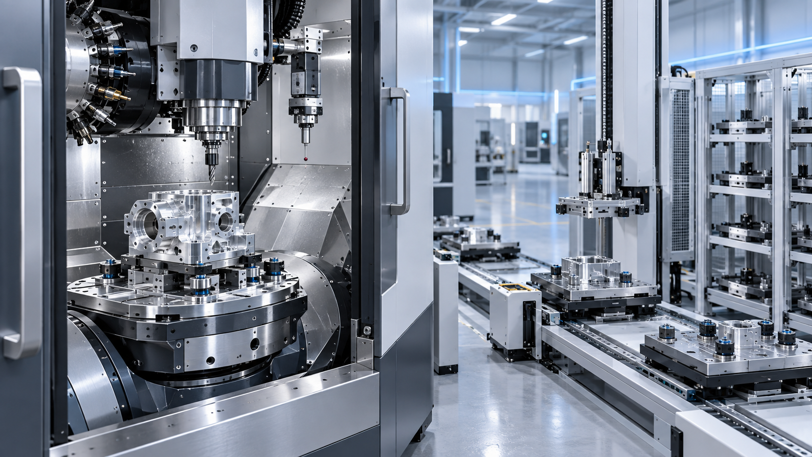
 How to Select CNC Equipment for High-Mix, Low-Volume ProductionCNC Machining Technology Center
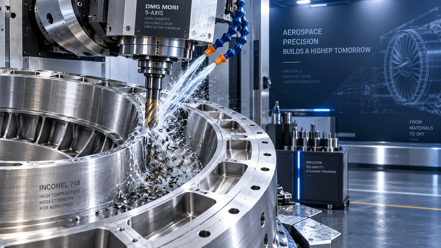
 Can CNC Machining Inconel Control Tool Wear in High-Temperature Aerospace Parts?CNC Machining Technology Center
 Machine Tool Market Outlook: Demand Drivers, Capacity Shifts, and Investment RisksManufacturing Market Research Center
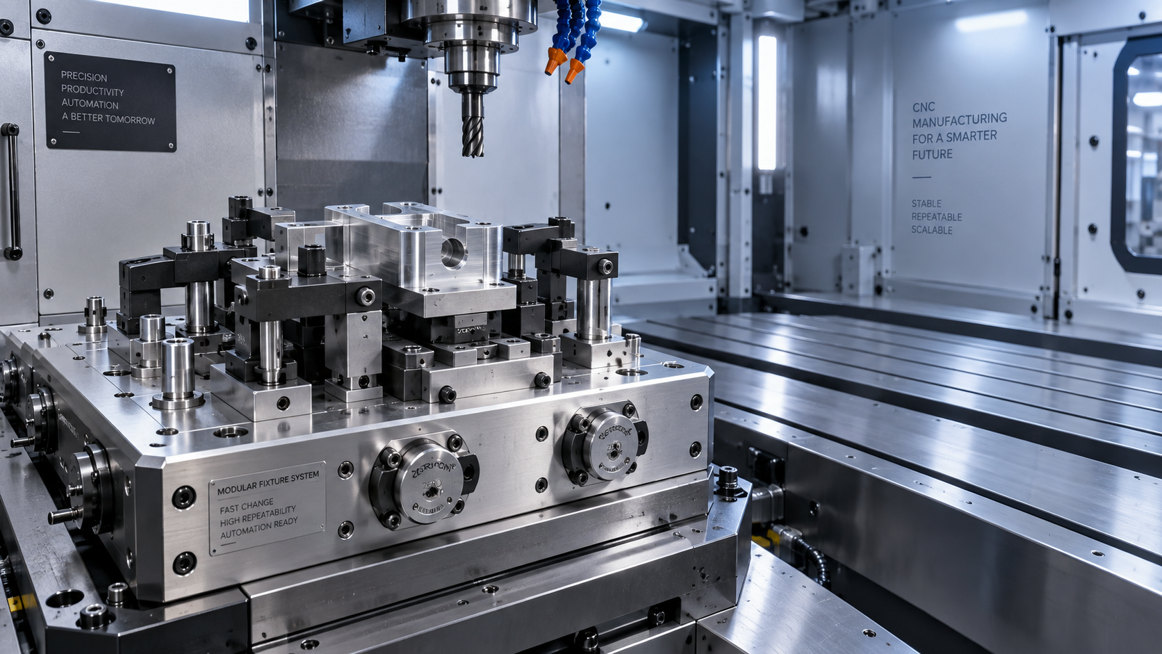
 Zero-Point Clamping or Modular Fixtures? Choosing a Faster CNC Changeover SystemCNC Machining Technology Center

Aris Katos
Future of Carbide Coatings
15+ years in precision manufacturing systems. Specialized in high-speed milling and aerospace grade alloy processing.
▶
Smart Manufacturing for Small Businesses: Where Automation Delivers the Fastest ROIMachine Tool Industry Editorial Team▶
How Smart Manufacturing Technology Improves OEE Across Industry 4.0 Production LinesMachine Tool Industry Editorial Team▶
How to Evaluate an Automation Line for Electronics Production Before InvestmentMachine Tool Industry Editorial Team▶
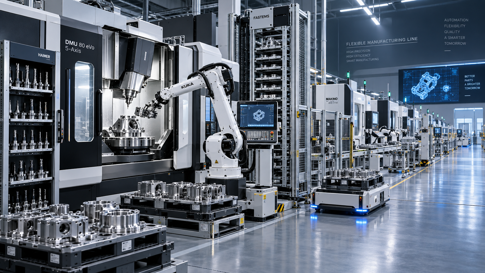
How to Evaluate an Automated Production Line for Output, Flexibility, and ROIMachine Tool Industry Editorial Team▶
How Smart Manufacturing Improves Traceability and Quality Control in Aerospace?Machine Tool Industry Editorial Team
Mastering 5-Axis Workholding Strategies
Join our technical panel on Nov 15th to learn about reducing vibrations in thin-wall components.

Providing you with integrated sanding solutions
Before-sales and after-sales services
Comprehensive technical support