• Global CNC market projected to reach $128B by 2028 • New EU trade regulations for precision tooling components • Aerospace deman
NYSE: CNC +1.2%LME: STEEL -0.4%

CNC Technology Explained: Key Motion Control, Accuracy, and Toolpath Basics
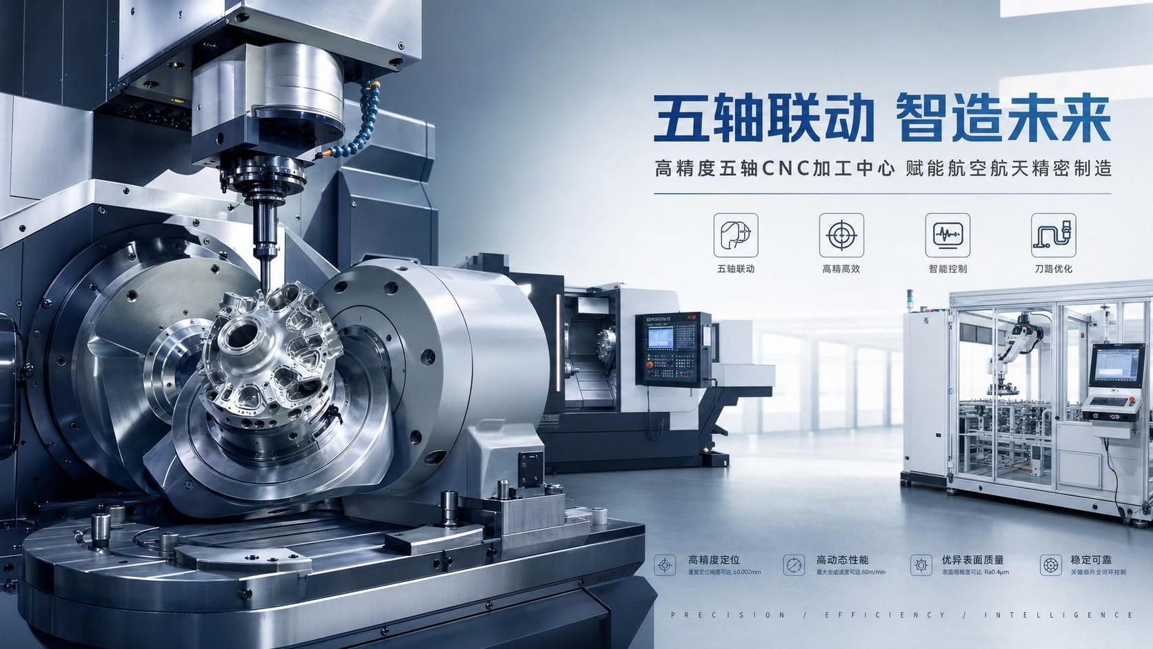
CNC technology sits at the center of modern machining because it turns design intent into controlled, repeatable movement. In daily production, that matters far beyond programming theory. It affects whether a bore stays in tolerance, whether a surface finish remains stable, and whether an automated line keeps running without constant correction.
Across automotive, aerospace, energy equipment, and electronics production, CNC lathes, machining centers, and multi-axis systems now support both precision and throughput. As factories push toward digital integration and flexible production, a practical understanding of motion control, accuracy, and toolpath behavior has become a basic requirement for reliable machining results.
Why CNC technology matters more now
The machine tool industry is moving toward tighter tolerances, shorter cycle times, and higher automation. That shift is visible in global manufacturing hubs, especially in China, Germany, Japan, and South Korea, where machine tools, tooling, controls, and production systems are developing together.
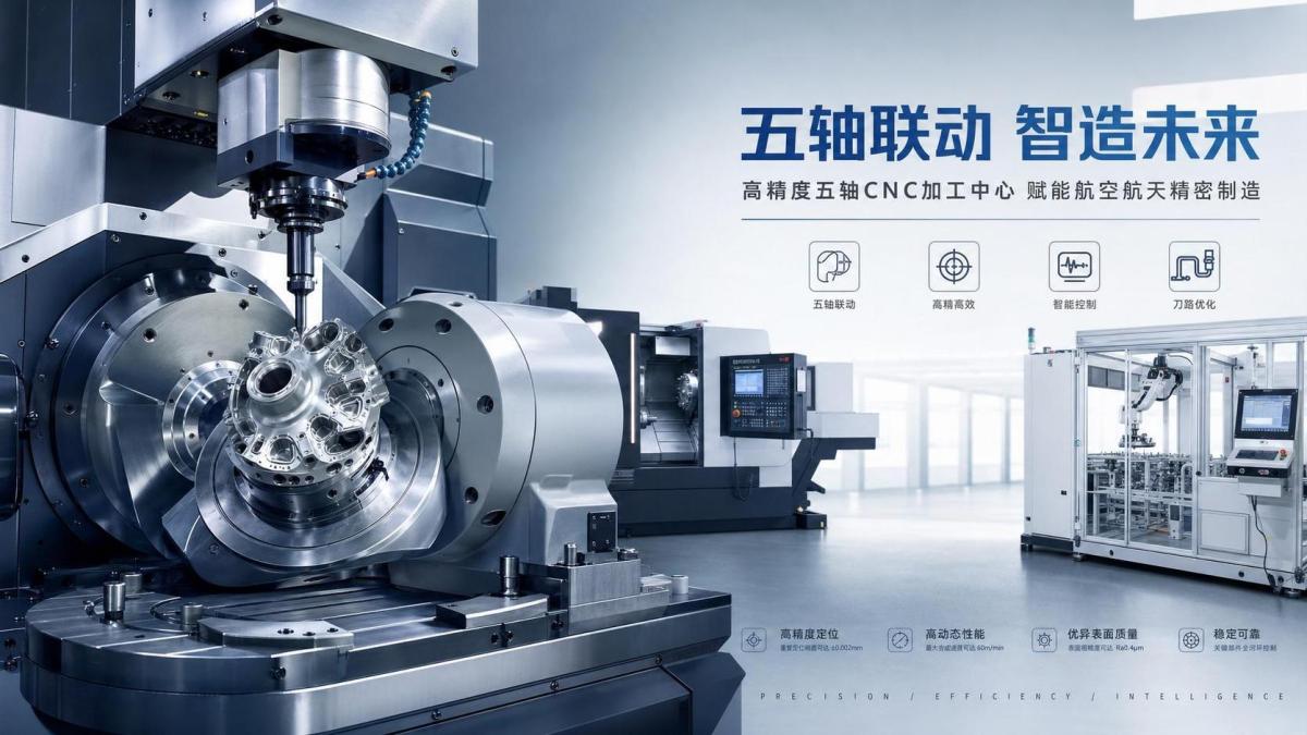
In this environment, CNC technology is no longer only about cutting metal accurately. It also connects with robots, fixture systems, probing, tool management, and production data. A small error in axis behavior or toolpath planning can spread into scrap, downtime, and unstable batch quality.
That is why the basics deserve attention. Better understanding at the machine level often leads to faster setup, fewer alarms, and more consistent parts without major capital changes.
Motion control is the core of machine behavior
At its simplest, motion control is how the CNC system commands each axis to move in position, speed, and timing. Every cut depends on that coordination. Linear axes, rotary axes, spindle motion, and feed commands must work together without lag that affects the part.
Servo systems, encoders, ball screws, guideways, and controller parameters all shape the final result. Even when a program looks correct, poor acceleration settings or backlash compensation can change how the tool reaches a feature.
What operators usually notice first
Motion problems often appear as inconsistent dimensions, witness marks at corners, chatter during direction changes, or unstable finishes on circular interpolation. These symptoms can seem like tooling issues, yet the real cause may sit inside the motion system.
CNC technology works best when commanded motion and actual motion stay close. The wider that gap becomes, the harder it is to hold tolerance on repeat runs.
Key motion factors to watch
- Axis acceleration and deceleration during corners and short moves
- Backlash or lost motion on worn mechanical components
- Servo tuning that is too aggressive or too soft
- Spindle synchronization in turning, threading, and rigid tapping
- Thermal drift after long production cycles
Accuracy is more than a machine specification
Catalog accuracy and actual production accuracy are not always the same. A machine may have strong positioning capability, yet real output still depends on setup quality, workholding rigidity, tool condition, material variation, and environmental stability.
In practical terms, CNC technology supports accuracy through a chain of controls. Programming, machine calibration, fixture repeatability, probing routines, and offset management all contribute. If one link becomes weak, stable tolerance becomes difficult even on advanced equipment.
Different kinds of accuracy affect different jobs
This is especially important in precision manufacturing, where parts may pass initial inspection but drift later in the shift. Looking only at first-piece quality can hide a deeper process problem.
Toolpath basics shape quality and cycle time
A toolpath is the planned route the cutter follows through material. In CNC technology, toolpaths influence more than machining time. They also affect cutting load, heat generation, vibration, tool life, chip evacuation, and final surface condition.
Simple toolpaths may work for simple features, but high-value parts usually need smarter path control. This is common in multi-axis machining, deep cavities, thin walls, and contour finishing where abrupt direction changes can damage both efficiency and accuracy.
Common toolpath choices and their effect
- Zigzag paths remove material quickly but may leave marks at reversals
- Contour-parallel paths support finish quality on shaped surfaces
- Trochoidal or adaptive paths reduce tool load in harder materials
- Constant engagement paths help maintain steady cutting conditions
- Lead-in and lead-out choices affect edge quality and tool wear
Usually, the best toolpath is not the shortest visual path. It is the one that keeps the process stable while meeting dimensional and surface requirements.
Where these basics show up in real production
In turning, motion control and spindle synchronization directly affect roundness, taper control, and thread quality. On shafts and precision discs, even a small mismatch between feed and spindle response can produce visible defects.
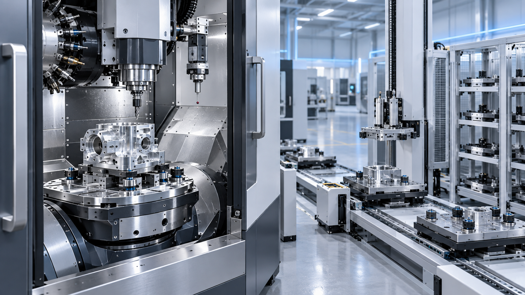
In machining centers, CNC technology becomes critical when multiple faces, hole patterns, and tight datums must align in one setup. Toolpath strategy and fixture access then become just as important as raw spindle power.
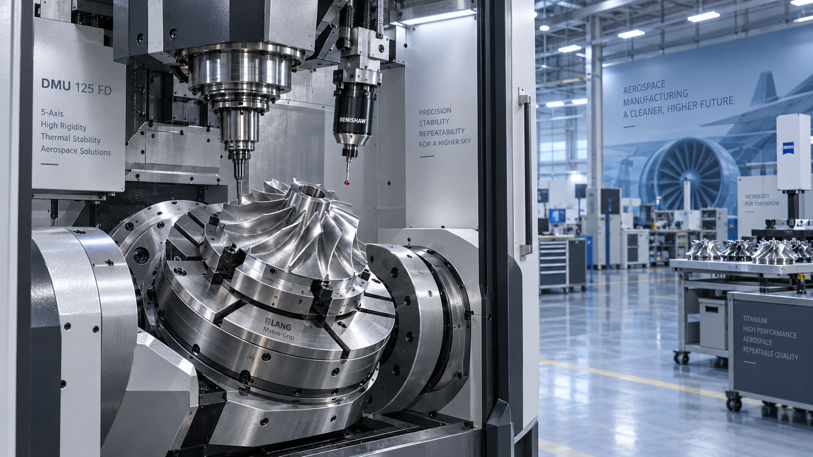
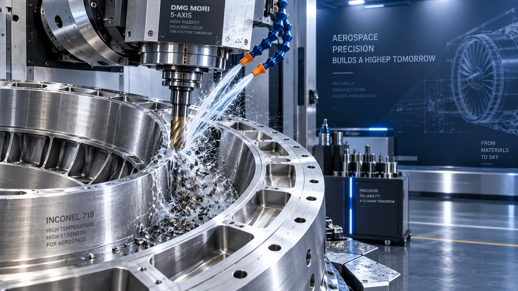
For multi-axis systems, the challenge increases. Rotary axis accuracy, collision avoidance, tool orientation, and post-processor quality all affect the final part. This is common in aerospace structures, impellers, molds, and complex energy components.
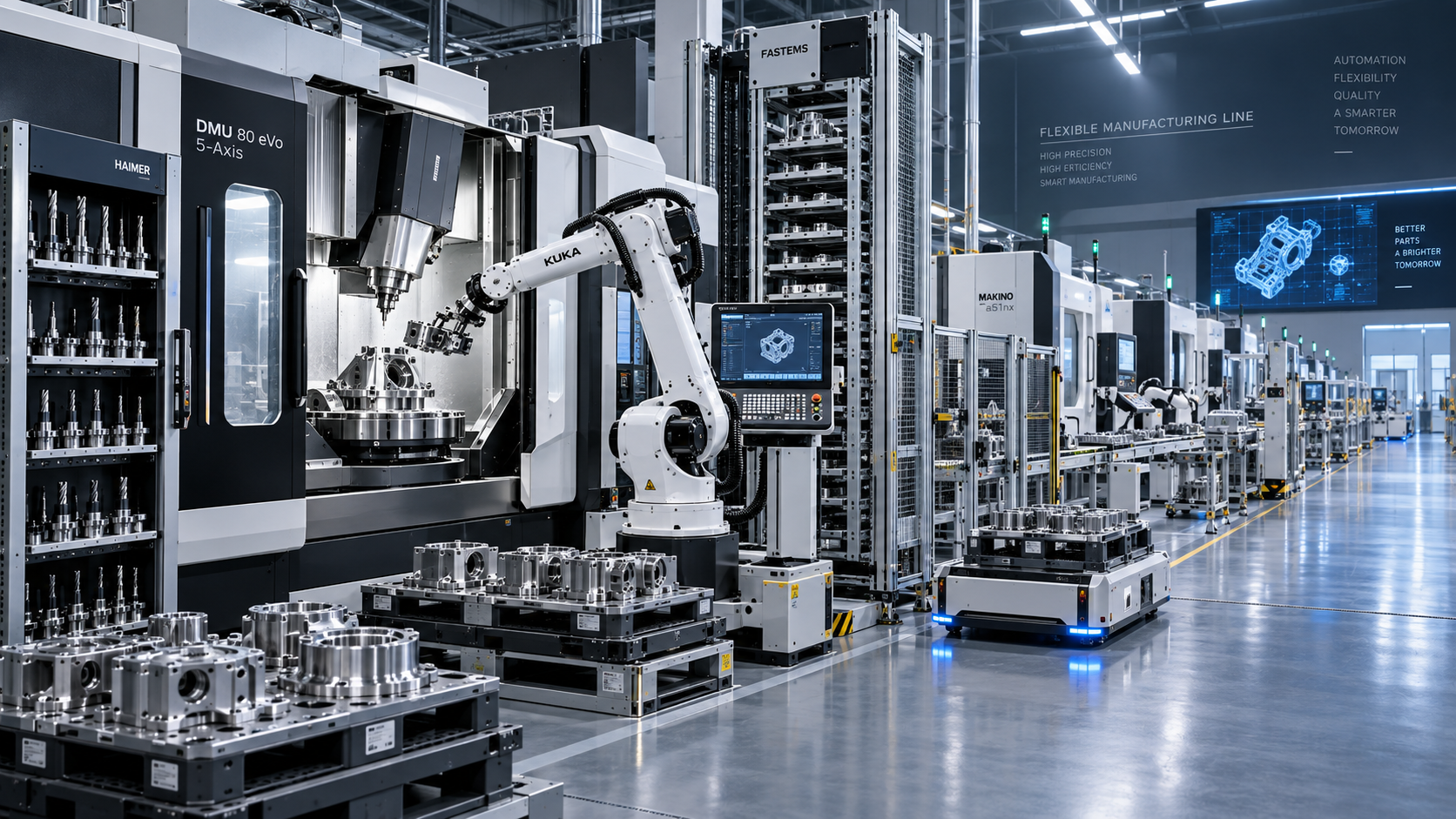
In automated lines, the same principles apply at a larger scale. Poor repeatability from one station can interrupt downstream robots, probing stations, or assembly steps. A single unstable machining process can weaken the entire production flow.
What to check when results are inconsistent
When part quality changes without an obvious cause, it helps to separate the problem into motion, tooling, setup, and data. That keeps troubleshooting focused and prevents repeated offset changes that only hide the issue.
A practical review sequence
- Compare actual dimensions across several cycles, not only one part
- Check machine warm-up condition and recent maintenance records
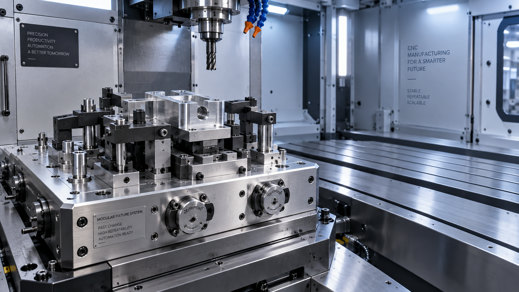
- Verify workholding contact points and clamping repeatability
- Inspect tool wear pattern instead of only tool age
- Review feed transitions, arc settings, and corner behavior in the program
- Confirm offsets, probe data, and compensation values were updated correctly
Many recurring defects come from interaction between systems, not one isolated mistake. CNC technology rewards that broader view because machine behavior, software logic, and physical cutting are always linked.
How to use CNC technology more effectively
The strongest results usually come from standardizing a few habits. Keep proven programs under revision control. Record stable cutting conditions by material and tool family. Use probing and verification data to support setup decisions instead of relying on repeated manual correction.
It also helps to connect machine performance with production goals. If cycle time is the only target, accuracy and tool life may suffer. If tolerance is protected without attention to path efficiency, output can fall below line requirements. Good CNC technology decisions balance both sides.
As smart factory practices expand, digital monitoring will continue to matter more. Trend data from servo loads, spindle loads, probe checks, and tool consumption can reveal process drift before scrap rises. That is where basic understanding turns into better control.
A useful next step is to review one recurring part family through three lenses: motion behavior, accuracy risk, and toolpath efficiency. That kind of structured comparison often shows where the largest improvement opportunity really sits.
Recommended for You
 CNC Machine Arrival Inspection: Check Shipping Damage, Accuracy, Safety, and DocumentsCNC Machining Technology Center
 How to Select a Machine Tool for Aerospace Parts with Tight Tolerances?Machine Tool Industry Editorial Team
 How to Select CNC Equipment for High-Mix, Low-Volume ProductionCNC Machining Technology Center
 Can CNC Machining Inconel Control Tool Wear in High-Temperature Aerospace Parts?CNC Machining Technology Center
 Machine Tool Market Outlook: Demand Drivers, Capacity Shifts, and Investment RisksManufacturing Market Research Center
 Zero-Point Clamping or Modular Fixtures? Choosing a Faster CNC Changeover SystemCNC Machining Technology Center

Aris Katos
Future of Carbide Coatings
15+ years in precision manufacturing systems. Specialized in high-speed milling and aerospace grade alloy processing.
▶
How to Select CNC Equipment for High-Mix, Low-Volume ProductionCNC Machining Technology Center▶
Can CNC Machining Inconel Control Tool Wear in High-Temperature Aerospace Parts?CNC Machining Technology Center▶
How Automated Precision Machining Maintains Tolerance in High-Mix ProductionCNC Machining Technology Center▶
CNC Programming Explained: From CAD Models to Reliable Shop-Floor ToolpathsCNC Machining Technology Center▶
How Multi-Axis Machining Produces Complex Components With Fewer SetupsCNC Machining Technology Center
Mastering 5-Axis Workholding Strategies
Join our technical panel on Nov 15th to learn about reducing vibrations in thin-wall components.

Providing you with integrated sanding solutions
Before-sales and after-sales services
Comprehensive technical support