• Global CNC market projected to reach $128B by 2028 • New EU trade regulations for precision tooling components • Aerospace deman
NYSE: CNC +1.2%LME: STEEL -0.4%

What Is a Turning Center? Capabilities, Components, and Applications
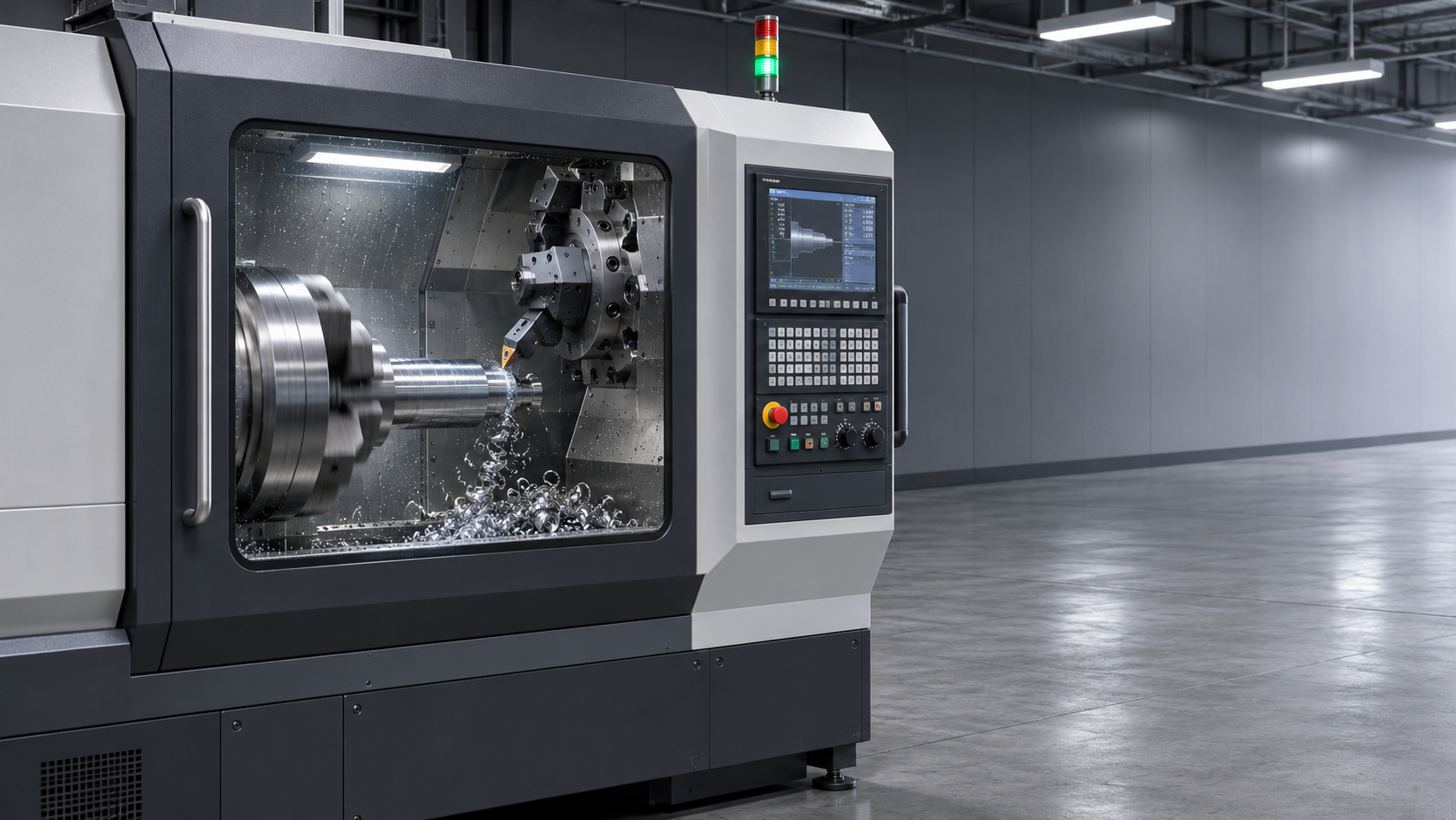
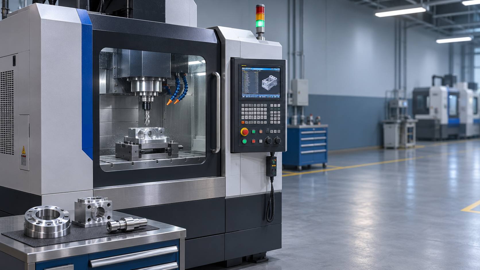
A turning center is a CNC machine tool designed to shape rotating workpieces with precision, often combining turning with operations such as drilling and milling. From automotive shafts to aerospace components, these machines help manufacturers produce accurate parts efficiently and consistently. Understanding how a turning center works, which components support its capabilities, and where it is used can help engineers, buyers, and manufacturing professionals evaluate its role in modern production.
What Makes a Turning Center Different?
At its most basic, a turning center holds and rotates a workpiece while a cutting tool removes material. The tool follows programmed movements to produce features such as outside diameters, faces, grooves and threads. Unlike a manually operated lathe, the machine uses computer numerical control, or CNC, to coordinate spindle rotation, tool movement and changes between operations.
The terms CNC lathe and turning center are often used interchangeably, and there is no universally applied dividing line between them. In practice, “turning center” often suggests a CNC lathe with a tool turret, an enclosed work area and, in many configurations, additional capabilities such as driven tools or a secondary spindle. A machine described as a CNC lathe can also have some of these features, so the specification matters more than the label.
The distinction becomes useful when a part needs more than round surfaces. A conventional turning setup can make a shaft with several diameters and a threaded end. If the same shaft also needs cross-holes or milled flats, a suitably equipped turning center may perform those features before the part leaves the machine.
How the Machine Works
A typical cycle begins with a workpiece secured in a chuck or collet on the main spindle. The CNC program calls up a tool, starts the spindle and moves the cutting edge along programmed paths. On a basic two-axis machine, the X axis generally controls movement toward or away from the spindle centerline, while the Z axis runs along the spindle’s length.
A roughing tool may remove most of the excess material, followed by finishing tools that bring surfaces closer to the required dimensions and finish. Other tools can drill a central hole, cut a groove or form a thread. The actual sequence depends on the material, shape, tolerances and how securely the part can be held.
For features that are not rotationally symmetrical, the spindle may stop at a programmed angle or rotate under controlled positioning. A driven tool can then drill or mill the workpiece. This capability depends on the machine configuration: a standard turning turret does not automatically provide live tooling, spindle positioning or additional linear axes.
The Components Behind the Cutting Cycle
The spindle and workholding system determine how the part is presented to the cutting tools. A chuck is common for individual blanks and larger workpieces; a collet is often used for suitable bar stock or smaller parts. The right choice depends on grip, access, part geometry and the risk of distortion. A thin-walled sleeve, for example, can deform if clamping pressure is excessive, even when the cutting program is sound.
The turret holds the tools and indexes them into position. Its capacity matters when a part requires several turning, boring, drilling and milling tools. Tool positions alone do not tell the whole story: driven-tool availability, tool interference and the space needed for holders can limit which tools are usable in a particular setup.
The machine bed, guideways and axis drives support and position the moving assemblies. Their condition and design affect how well the machine handles cutting forces and maintains accuracy. The CNC control interprets the program and manages the axes, spindle and machine functions; probes, tool setters and monitoring systems may be added to support setup and inspection.
Coolant delivery and chip removal deserve attention too. Long, tangled chips can interfere with a workpiece or tool, particularly during unattended operation. A chip conveyor, appropriate cutting tools and a suitable coolant strategy can help, but chip behavior still varies with material and cutting conditions.
Which Operations Can It Perform?
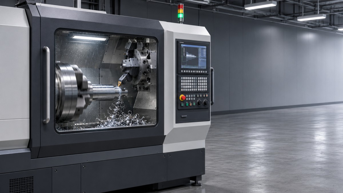
Turning centers are strongest when the part is organized around an axis of rotation. Common operations include facing the end of a blank, turning external diameters, boring internal diameters, grooving, threading and parting a finished component from bar stock. A boring operation enlarges or finishes an existing hole; drilling generally creates the initial hole.
With live tooling, the range expands to operations such as drilling radial holes and milling flats or slots. Some machines add a Y axis, allowing certain features to be machined away from the spindle centerline. A C axis provides controlled angular positioning of the spindle. These features are useful, but they are not interchangeable: the required motion depends on the geometry being produced.
A subspindle can grip a part after the main-spindle operations and present its opposite end to the tools. This makes it possible to complete more of a component without manually transferring it to another setup. The transfer itself still needs careful programming and workholding design, especially when the two ends must relate accurately to each other.
More capability does not make every job simpler. A part with extensive prismatic surfaces, deep pockets or complex access requirements may be better suited to a machining center, or to a process that combines turning and milling on separate machines. The best route depends on the part, not on the number of axes in the brochure.
Horizontal, Vertical and Multitasking Configurations
A horizontal turning center has a spindle oriented horizontally and is a familiar choice for shafts, bushings and bar-fed parts. Long, slender workpieces may need a tailstock or steady rest for support; without it, cutting forces can cause deflection and affect diameter or surface finish. The practical limit depends on the part and the operation, not just the machine’s stated maximum length.
A vertical turning center holds the workpiece with its rotational axis vertical. This arrangement can be useful for large, heavy, disc-shaped parts because the workpiece rests on a horizontal chuck or table. Loading equipment and chip evacuation still need to be considered when planning the cell.
More complex multitasking machines combine turning with extensive milling capability and may include multiple tool carriers or spindles. They can reduce handling between operations, but they also demand more programming, setup planning and collision awareness. For a straightforward turned component, a simpler machine may be easier to keep productive and maintain.
Where Turning Centers Are Used
In automotive production, turned components can include shafts, sleeves, hubs and threaded parts. Repeatable workholding and reliable chip control matter when the same geometry is produced over many cycles. Bar feeders and part catchers can reduce manual intervention for suitable components, although their usefulness depends on the stock form and the part’s size and shape.
Aerospace work can involve rings, fittings and other rotational components made from materials that place demanding requirements on tools and process control. A machine’s ability to combine operations may reduce transfers, but finishing requirements, inspection access and material behavior still determine the machining plan.
Energy equipment may use large flanges, valve components and heavy shafts, where workpiece weight and clamping become central considerations. Electronics and precision equipment can involve much smaller connectors, pins and housings, where burr control and delicate features deserve particular attention. These examples illustrate the range of applications; they do not imply that one machine configuration is equally suited to all of them.
Why Fewer Setups Help—and Where the Limits Are
When turning, drilling and milling are completed in one workholding arrangement, features can be produced relative to the same setup. That can reduce handling and avoid some errors introduced when a part is removed and re-clamped. It can also shorten the route through a workshop by eliminating a separate milling operation.
But “one setup” is not the same as “no variation.” Tool wear, thermal changes, clamping pressure, material behavior and measurement methods can all affect the result. A subspindle transfer adds another gripping operation, and a machine may still require an external process for features it cannot reach or for finishing beyond its practical capability.
Cycle time also needs context. A combined process may save handling time while spending longer on the turning center itself. If a workshop already has available milling capacity, splitting the work could be the better production decision. Comparing only the cutting time on one machine can hide the cost of waiting, transfer, inspection and setup elsewhere.
What to Check When Evaluating a Machine
Start with representative drawings rather than a machine category. The largest stated turning diameter or length may not be available with every chuck, turret position or support arrangement. Check the usable working envelope with the intended fixture, tools and clearance for loading—not just the headline capacity.
Look closely at the features that drive the process:
- Workholding and access: Can the chuck or collet grip the part securely without blocking critical surfaces or distorting thin sections?
- Spindle and tool capability: Are the available torque, speed, driven-tool positions and axis movements appropriate for the material and features?
- Accuracy requirements: Which dimensions and relationships are critical, and how will they be measured during production? Published machine figures should be checked against the relevant operating conditions and project requirements.
- Production support: Will the job need a bar feeder, tailstock, steady rest, probe or automated loading? Each addition affects the layout and setup.
- Ownership and support: Are suitable tooling, spare parts, service and operator skills available where the machine will be installed?
Automation and digital integration are increasingly common in CNC production, from robotic loading to machine-status monitoring. They are most useful when the underlying process is stable. If chips regularly jam, blanks vary excessively or tools wear unpredictably, adding automation may simply allow a problem to continue for longer before someone notices.
For an initial assessment, choose a few parts that reflect the work you expect to produce, including the awkward ones. Map their operations, clamping points and inspection needs. That exercise will reveal whether a basic CNC lathe, a live-tool turning center or a more capable multitasking machine is the sensible fit.
NEXT ARTICLE
Recommended for You
![]() Commerce Ministry: China-Switzerland FTA Upgrade to Expand Market for Swiss Machine ToolsGlobal Machine Tool Trade Research Center
 What Is a Turning Center? Capabilities, Components, and ApplicationsCNC Machining Technology Center
 CNC Milling Spindle Speed for Titanium: How to Calculate RPMCNC Machining Technology Center
 How Precise Are Modern CNC Shops? Tolerances and Their LimitsCNC Machining Technology Center
![]() Report: 56% of China's Key Steelmakers Lost Money in SeptemberManufacturing Market Research Center
 Machine Tool Prices: Is a CNC Upgrade Worth the Investment?Manufacturing Market Research Center


Aris Katos
Future of Carbide Coatings
15+ years in precision manufacturing systems. Specialized in high-speed milling and aerospace grade alloy processing.
▶
What Is a Turning Center? Capabilities, Components, and ApplicationsCNC Machining Technology Center▶
Manual vs. CNC Lathe for Simple Parts: How Batch Size Affects the ChoiceCNC Machining Technology Center▶
How Do You Evaluate a CNC Lathe's Repeat Positioning Accuracy?CNC Machining Technology Center▶
How to Select a CNC Metal Lathe for Tight-Tolerance Shaft and Sleeve PartsCNC Machining Technology Center▶
CNC Lathe Quick Installation Guide: Alignment Checks Before First Production RunCNC Machining Technology Center
▶
Mastering 5-Axis Workholding Strategies
Join our technical panel on Nov 15th to learn about reducing vibrations in thin-wall components.

Providing you with integrated sanding solutions
Before-sales and after-sales services
Comprehensive technical support