• Global CNC market projected to reach $128B by 2028 • New EU trade regulations for precision tooling components • Aerospace deman
NYSE: CNC +1.2%LME: STEEL -0.4%

How Multi-Axis Machining Produces Complex Components With Fewer Setups
How Multi-Axis Machining Produces Complex Components With Fewer Setups
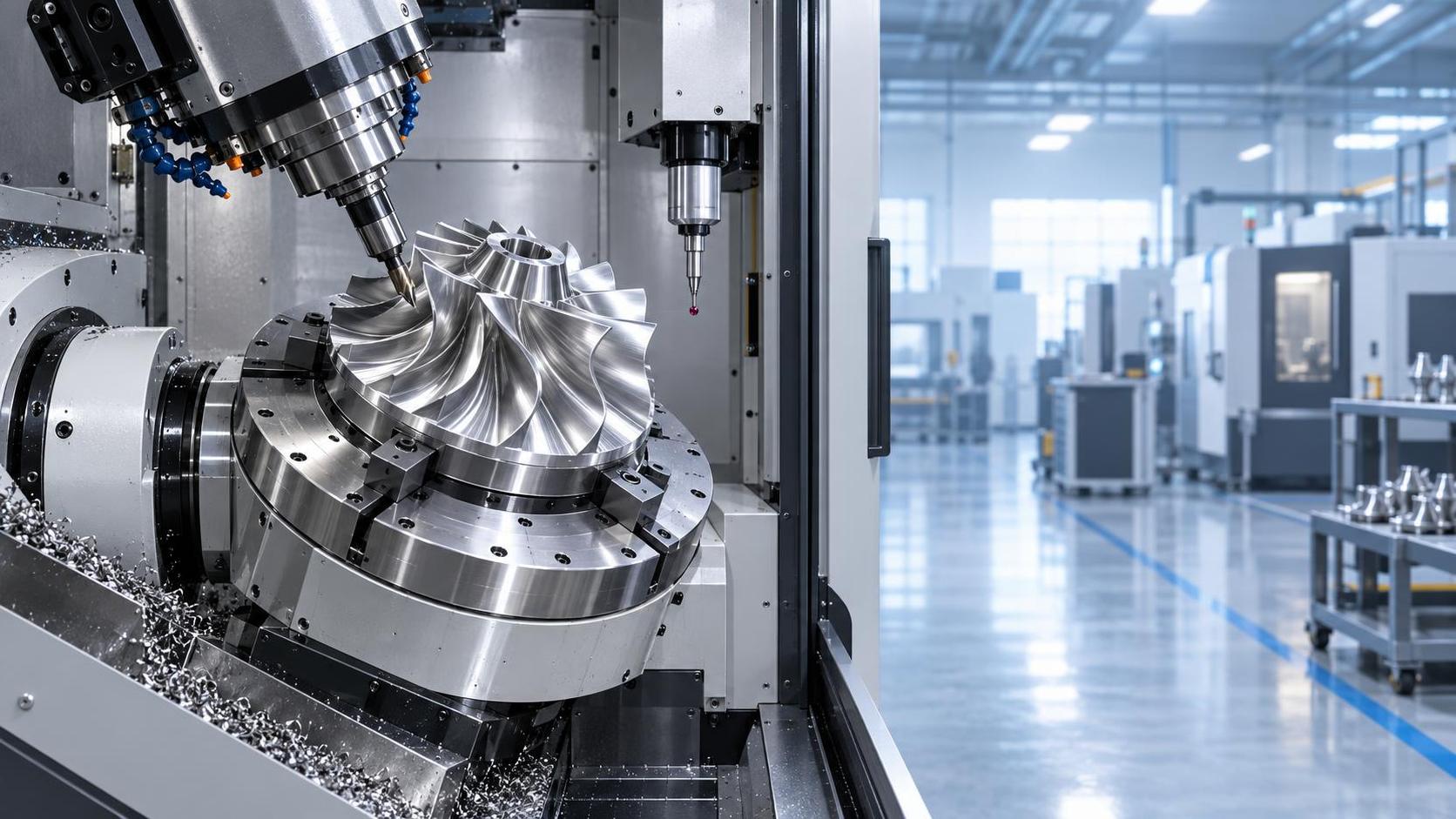
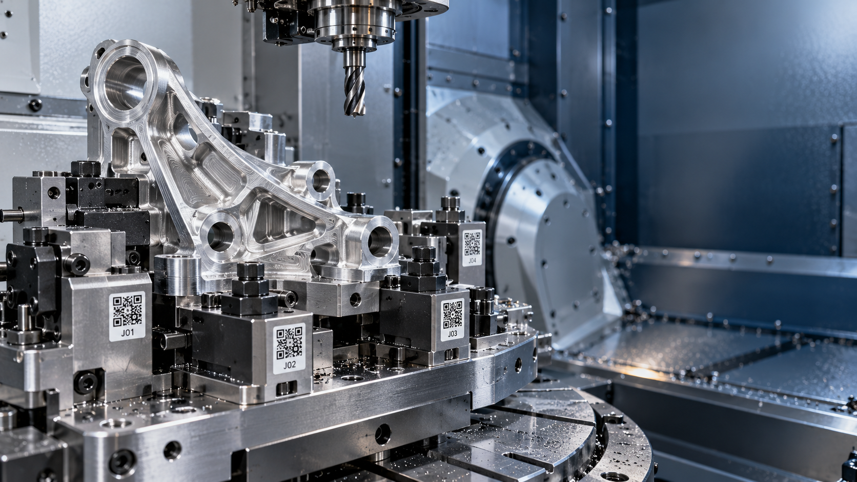
For technical evaluators assessing precision, cycle time, and process stability, the Multi-axis Machining Process for complex components offers a practical route to reduce setups without sacrificing accuracy. By enabling multiple surfaces, angles, and features to be machined in a single clamping, multi-axis systems can improve part consistency, minimize repositioning errors, and streamline production of demanding aerospace, automotive, energy, and industrial components.
The value is not simply that a machine has more axes. The real question is whether the complete process—from datum strategy and fixture design to tool access, probing, machining sequence, and inspection—can hold the required geometry with fewer handoffs. A five-axis machine can still create unstable results if the workholding is weak, the rotary axes are poorly calibrated, or the CAM strategy ignores tool deflection. Conversely, a well-planned multi-axis process can eliminate several operations that would otherwise require separate fixtures, manual alignment, and repeated first-off inspection.
This distinction matters as machine tool users move toward higher precision, greater automation, and more digital process control. CNC lathes, machining centers, mill-turn platforms, automated pallet systems, cutting tools, and fixtures are increasingly evaluated as connected elements of a production system rather than isolated purchases.
Why Setup Reduction Has a Direct Effect on Accuracy
Every time a part is unclamped and moved, a new stack of variation is introduced. The operator may establish a different datum. A fixture may locate against a surface that already contains machining variation. Chips, burrs, thermal drift, jaw wear, and inconsistent clamping force can alter the next operation. Even when each individual setup is controlled, the accumulated relationship between features can become difficult to protect.
This is especially visible in parts with compound-angle holes, intersecting bores, contoured surfaces, thin walls, or features located around a central axis. A conventional three-axis route may machine one face, remove the component, index it in a second fixture, then repeat the cycle for angled or side features. The absolute dimensions may remain acceptable while positional relationships between those features become the real source of rejection.
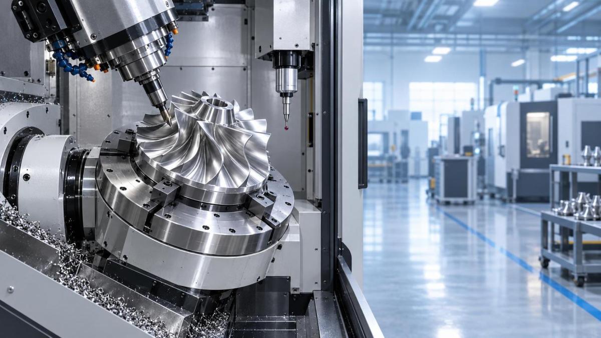
A multi-axis system keeps more of the part’s geometric relationships inside one coordinate framework. The machine rotates or tilts the workpiece, the tool, or both, allowing features on several orientations to be reached from the original clamping. That does not eliminate all error, but it removes error sources associated with manual transfer and repeated re-datuming.
For complex components, fewer setups also improve traceability. When roughing, semi-finishing, finishing, probing, and some in-process verification occur in one controlled program, it is easier to connect a dimensional result to a specific tool, offset, machine state, and process step. This becomes increasingly useful in automated cells, where repeatability depends on predictable loading, identification, and offset management.
Three-Axis, 3+2, Simultaneous Five-Axis, and Mill-Turn Are Different Decisions
“Multi-axis” is often used too broadly in early project discussions. Technical evaluation should separate indexed machining from true simultaneous motion, and milling-centered processes from turning-centered processes. Each option can reduce setups, but not to the same extent or for the same part geometry.
For many components, 3+2 machining is the most practical first step. It allows several faces to be machined in one clamping, often using shorter and more rigid tools than a fixed three-axis arrangement would permit. It can reduce setup count substantially without the continuous rotary-axis motion, programming complexity, and surface-management demands of simultaneous five-axis machining.
Simultaneous five-axis motion becomes more compelling when the cutter must maintain a changing orientation relative to a curved surface, avoid holder interference in deep regions, or control contact conditions on thin or highly contoured sections. It is not automatically faster. The time saved in setups may be offset by slower feed rates, cautious collision margins, additional simulation work, or lengthy finishing passes. The comparison has to be made at process-route level, not by machine cycle alone.
The Datum Plan Should Be Reviewed Before Machine Capacity
A common mistake is to start with axis count: “Can this five-axis machine reach every feature?” Reach is necessary, but it is not the first engineering question. The first question is which datums control the critical functional relationships and whether those datums can be established, protected, and inspected in the planned clamping.
Consider a structural component with a sealing face, a precision bore, and several angled mounting holes. If the bore and sealing face are the functional references, the fixture should locate the workpiece in a way that supports their relationship throughout the relevant machining sequence. Finishing an angled hole in one setup is of limited benefit if the part must later be relocated to establish the bore from another reference.
The fixture must also account for cutting loads and changing part stiffness. Multi-axis access can tempt programmers to machine features from numerous directions, but each new tool orientation changes the force path through the part and fixture. Thin-wall aerospace structures, energy-sector valve components, and precision electronic housings may distort when clamping is excessive or when material removal is not balanced. In these cases, fewer setups do not mean fewer engineering decisions.
Probe strategy is part of the process, not an add-on
On-machine probing can establish stock position, confirm fixture seating, update work offsets, and detect certain deviations before a finishing operation begins. It is particularly valuable where castings, forgings, or welded blanks have variable stock conditions. However, probing should not be treated as a substitute for a defined datum scheme or final inspection method. Probe repeatability, stylus access, thermal conditions, calibration routines, and the measurement uncertainty required by the drawing all need review.
For tightly controlled features, an external coordinate measuring machine or another validated inspection method may still be required. The important point is to align machining and measurement references. If the machine uses one theoretical datum structure while inspection uses another, the production team can spend unnecessary time reconciling results that are not directly comparable.
Where the Process Can Lose Stability
Reduced setup count is not a guarantee of reduced risk. In fact, concentrating many operations in one cycle can make a failure more consequential. A problem discovered near the end of a long multi-axis cycle may affect a part that has already accumulated significant machining time. Process stability depends on identifying the most likely failure modes early.
- Rotary-axis positioning and kinematic compensation should be verified against the part tolerance, particularly when machining features at several orientations.
- Tool length, holder geometry, and machine-envelope checks need to be included in CAM simulation; a valid cutter path is not enough if the holder, spindle nose, fixture, or tailstock can interfere.
- Long-reach tools can solve access problems while introducing chatter, taper, poor surface finish, or inconsistent bore geometry.
- Thermal behavior deserves attention on large parts or long unattended cycles. Machine warm-up, spindle growth, coolant condition, and ambient variation can influence repeatability.
- Chip evacuation changes as the part is tilted. Deep pockets, blind cavities, and interrupted cuts can retain chips that damage finished surfaces or disrupt probing.
Machine configuration influences these risks. A trunnion-style table may provide excellent access for smaller parts but can impose limits on workpiece size and rotary-axis loading. A swivel-head configuration may suit larger workpieces and preserve table capacity, while introducing different dynamics and collision considerations. There is no universal arrangement that is superior without reference to component mass, envelope, material, feature distribution, and tolerance requirements.
What to Request During a Technical Evaluation
A credible assessment should go beyond a machine brochure and a nominal axis-travel comparison. Ask for a proposed operation sequence showing the intended clamping points, primary datums, roughing and finishing order, tools requiring extended reach, and features that remain inaccessible. This makes it possible to distinguish an achievable concept from a robust production route.
The machine’s acceptance and verification approach should also be clear. ISO 230 provides a family of test methods for machine-tool performance, while ISO 10791 addresses testing for machining centres. Their relevance depends on the machine type, the applicable revision, the purchase specification, and the performance characteristics being evaluated. A general standard reference is not equivalent to proving that a particular part tolerance will be held under production conditions.
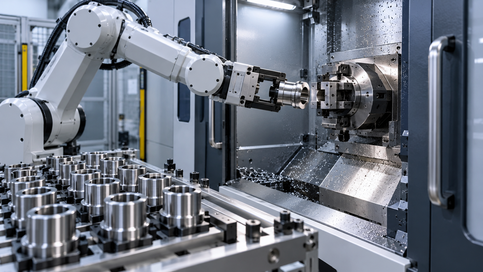
Useful questions include whether rotary-axis performance is measured and documented, how kinematic calibration is performed, what compensation functions are available, and how the supplier proposes to demonstrate machining capability on representative geometry. Where automation is planned, the review should extend to pallet repeatability, fixture identification, tool-life monitoring, recovery after interruption, and the traceability of offset changes.
Setup Reduction Is a System-Level Decision
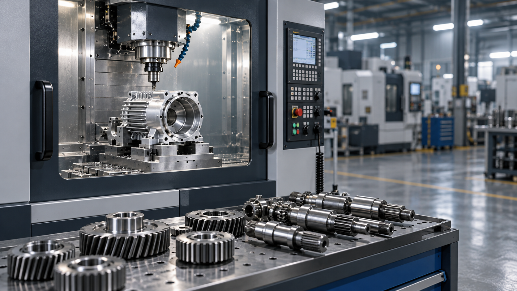
The strongest Multi-axis Machining Process for complex components is rarely the one with the most elaborate motion. It is the one that protects functional datums, avoids unnecessary transfers, keeps tools rigid, gives chips a reliable exit path, and produces an inspection result that can be traced back to the machining route. For a complex shaft, disc, impeller, structural bracket, or precision housing, the correct answer may be 3+2 machining, full simultaneous five-axis machining, or a mill-turn process.
As global machine tool manufacturing continues to develop across major industrial clusters in China, Germany, Japan, South Korea, and other markets, equipment selection is increasingly tied to digital integration, automation readiness, service capability, and process knowledge. Technical evaluation should therefore begin with the component and its control requirements—not with axis count alone. A reviewed drawing, datum chain, fixture concept, CAM simulation, and inspection plan will reveal far more about achievable performance than a general claim of five-axis capability.
Recommended for You
![]() FANUC Invests $18 Million in Largest U.S. Corporate Automation Training CenterMachine Tool Industry Editorial Team
FANUC Invests $18 Million in Largest U.S. Corporate Automation Training CenterMachine Tool Industry Editorial Team Southeast Asia Machine Tool Market: Comparing Automotive Demand by CountryManufacturing Market Research Center
![]() Zhongshan Xiaolan Machinery Exhibition Opens With Global Product DebutsMachine Tool Industry Editorial Team
Zhongshan Xiaolan Machinery Exhibition Opens With Global Product DebutsMachine Tool Industry Editorial Team Automated Production Machining: Which Parts and Batch Sizes Are a Good Fit?Machine Tool Industry Editorial Team
![]() FANUC Links FIELD System Data with Copilot to Advance Shop-Floor Data UseCNC Machining Technology Center
FANUC Links FIELD System Data with Copilot to Advance Shop-Floor Data UseCNC Machining Technology Center Smart Manufacturing for Aerospace: Building Traceability Across CNC OperationsCNC Machining Technology Center


Aris Katos
Future of Carbide Coatings
15+ years in precision manufacturing systems. Specialized in high-speed milling and aerospace grade alloy processing.
▶
FANUC Links FIELD System Data with Copilot to Advance Shop-Floor Data UseCNC Machining Technology Center▶
Smart Manufacturing for Aerospace: Building Traceability Across CNC OperationsCNC Machining Technology Center▶
Choosing a CNC Machine for Mold Making: Accuracy, Rigidity, and Surface FinishCNC Machining Technology Center▶
How to Cut CNC Machining Energy Use per Part Without Longer Cycle TimesCNC Machining Technology Center▶
Will a Mazak CNC retrofit work with your existing servo drives?CNC Machining Technology Center
▶
Mastering 5-Axis Workholding Strategies
Join our technical panel on Nov 15th to learn about reducing vibrations in thin-wall components.

Providing you with integrated sanding solutions
Before-sales and after-sales services
Comprehensive technical support