• Global CNC market projected to reach $128B by 2028 • New EU trade regulations for precision tooling components • Aerospace deman
NYSE: CNC +1.2%LME: STEEL -0.4%

CNC Programming Explained: From CAD Models to Reliable Shop-Floor Toolpaths

CNC programming is the controlled translation of part geometry, tolerances, material behavior, workholding conditions, and machine limits into axis motions that remove material predictably. A CAD model alone does not contain enough information to produce a reliable component. It describes the intended final shape, while the program must define the stock condition, datum scheme, cutting sequence, tool approach, spindle behavior, feed control, clearance strategy, and inspection-relevant surfaces.
For precision work, a toolpath should be judged by the quality of the manufactured result rather than by its visual resemblance to the CAD model. Two programs can create the same nominal geometry while producing different surface finishes, cycle times, tool loads, positional errors, and risks of collision or chatter. The useful question is therefore whether the programmed process remains stable when material, tool wear, fixture stiffness, and machine dynamics are present.
From design geometry to machinable features
The programming workflow starts by reading the model as a manufacturing definition. Holes, pockets, fillets, thin walls, bearing seats, threads, deep cavities, and freeform surfaces do not demand the same machining approach. A shallow open pocket may allow high material removal with an adaptive roughing path, while a narrow closed pocket can force a smaller cutter, lower radial engagement, more tool deflection, and longer finishing time.
Dimensions also need interpretation. A nominal diameter does not state whether it is a functional fit, a cosmetic surface, or a feature that will be measured after a later process. If a bore is intended to locate another component, the programming route may reserve stock for boring or reaming after roughing. Finishing that bore with the same end mill used for bulk material removal may appear efficient in a simulation but often provides weaker control of size, roundness, and surface condition.
The model should be considered alongside the drawing, tolerance notes, material specification, stock form, and any supplied datum requirements. CAD geometry can contain small blended surfaces, imported gaps, duplicate faces, or ambiguous edges that do not affect visual display but can disrupt feature recognition and toolpath calculation. Repairing or simplifying geometry before programming is often preferable to compensating for unstable toolpath behavior later.
Datums establish the process, not just the setup
A work coordinate system connects the digital program to the physical part. Its origin and axis directions should correspond to surfaces that can be located repeatedly on the fixture. Selecting a convenient corner of raw stock may be acceptable for a simple one-operation plate, but it becomes weak when multiple setups must maintain relationships between machined faces.
For a part with a critical bore pattern referenced to a machined base face, the base face should normally be created and established early enough to support later positioning logic. Otherwise, each setup may inherit variation from saw-cut stock, casting irregularity, or clamping distortion. Programming cannot recover a datum relationship that the setup strategy has already lost.
Work offsets also require explicit control in multi-fixture or palletized production. A program that assumes one fixed zero point can run correctly on the first fixture and produce a shifted part on the next. Fixture-specific offsets, probing routines, and consistent fixture identifiers reduce this exposure, provided that the programmed coordinate structure matches the actual machine setup.
Tool selection changes the attainable result
Tool choice is a process decision rather than a catalog selection. Cutter diameter, flute count, corner geometry, projection length, coating, and holder interface affect how the programmed path performs. A large end mill may shorten roughing time in an open area but cannot reach a corner radius or avoid nearby walls. A long-reach tool provides access to a deep feature, yet its reduced stiffness can make the same feed and radial engagement unsuitable.
Tool length is especially easy to underestimate. The programmed cutter may clear the part model while the holder, collet nut, extension, or spindle nose does not. CAM collision checking should therefore use realistic holder assemblies and gauge lengths rather than generic tool shapes. Clearance above the cutting edge is not enough when machining deep walls, angled cavities, or features near fixture hardware.
Feed rate should not be interpreted independently. The meaningful cutting condition combines spindle speed, feed per tooth, axial depth, radial width of cut, tool geometry, coolant delivery, and material condition. A feed rate that appears conservative in millimeters per minute can still overload a cutter if spindle speed is low. Conversely, very light radial engagement at a high programmed feed may produce a chip load that remains reasonable, provided machine acceleration and tool rigidity support it.
Material condition matters as much as material name. Annealed, forged, heat-treated, cast, welded, or stress-relieved material may machine differently even when the specified alloy is the same. Interrupted cuts in cast surfaces, hard skin on forged stock, internal residual stress, and local weld zones can change tool load abruptly. Programs intended for repeat production should include a machining strategy that tolerates expected variation rather than relying on a single ideal stock condition.

Roughing paths must prepare the finishing operation
Roughing is not merely the fastest possible removal of excess stock. Its output is the condition presented to the finishing tool. Uneven remaining stock causes variable cutting force during finishing, which can lead to dimensional drift, witness marks, or deflection at corners. A rest-machining strategy should remove material left by larger tools while avoiding unnecessary recutting of already-machined surfaces.
Modern constant-engagement toolpaths can reduce abrupt direction changes and stabilize cutter loading in many prismatic features. Their value depends on correct parameter selection. If a path uses rapid directional changes beyond the machine's practical acceleration capability, the commanded feed may not be achieved. The displayed cycle-time estimate then becomes optimistic, and repeated deceleration can alter the actual chip load around tight corners.
Entry and exit motions deserve the same attention as the main cutting path. Plunging directly into solid material with a tool not designed for center cutting can damage the cutter immediately. Helical ramps, linear ramps, predrilled entry points, or appropriate drilling cycles are selected according to tool geometry, available space, and material. At the end of a finishing pass, an abrupt retract near a visible wall can leave a mark even when the central portion of the path is well controlled.
For thin walls and flexible features, machining order can determine whether the final dimensions are reachable. Removing surrounding support too early allows the wall to move under cutting load. Leaving temporary support, reducing finishing engagement, sequencing opposite sides thoughtfully, or using a separate low-force finishing pass can reduce distortion. The correct approach is linked to part geometry and clamping access; a generic low-feed strategy does not solve a weak workholding arrangement.
Multi-axis motion requires a machine-specific view
Multi-axis programming adds tool orientation as a variable. Tilting the tool can improve access, keep the cutting zone away from the tool center, and avoid holder interference. It also changes effective cutting diameter, contact point, axis travel, rotary-axis motion, and the likelihood of singularity-related behavior. A path that is smooth in a virtual model may require abrupt rotary movement near a machine's kinematic limits.
Post-processing is the stage that converts CAM motion into the control-specific program format. It must reflect the actual machine configuration: rotary axis arrangement, travel limits, tool-change behavior, probing cycles, coordinate transformations, feed interpretation, and supported control functions. Using a post intended for a similar machine is not a minor administrative substitution. Different pivot locations or rotary conventions can change the relationship between commanded motion and the physical cutting point.
Five-axis work also needs a clear distinction between simultaneous machining and indexed positioning. Indexed operations rotate the part to a fixed orientation before conventional milling. They are often easier to verify and can provide sufficient access for many angled features. Simultaneous motion is justified when surface continuity, reach, or collision avoidance requires continuous orientation changes. Applying it where indexing is adequate increases verification effort without necessarily improving the part.
Verification has several layers
Simulation is necessary, but a green simulation result is not proof that a program is ready for production. Geometry-based verification can reveal gouges, uncut material, excessive stock, and collisions between modeled components. It will not automatically prove that the stock is clamped correctly, the actual tool length matches the library value, the machine has sufficient rigidity, or coolant reaches a deep cutting zone.
A reliable release process separates the questions that simulation can answer from those that require setup confirmation and controlled proving. The following sequence keeps those decisions visible:
- Validate the imported geometry, stock definition, critical tolerances, and datum references before paths are generated.
- Confirm the tool library against assembled tools, including actual gauge lengths, holder shapes, insert orientation, and usable reach.
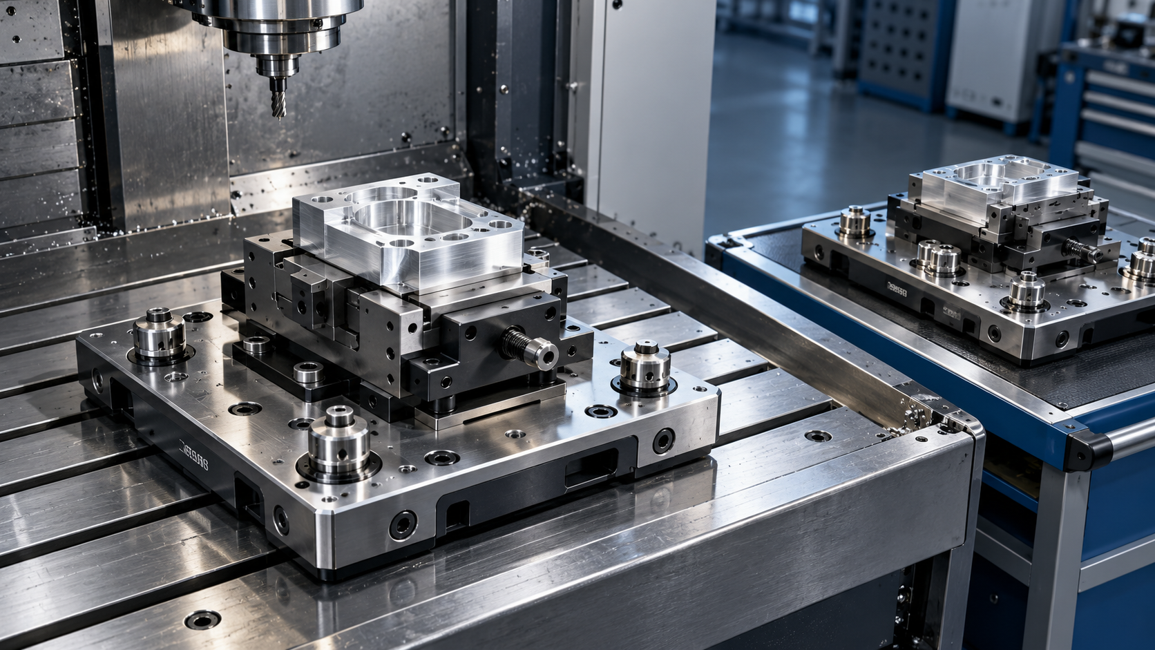
- Run collision and material-removal verification with fixtures, jaws, vises, clamps, and rotary components represented where they can affect motion.
- Review the posted NC code for offset calls, tool changes, spindle commands, coolant commands, safe planes, rotary positioning, and any control-specific macros.
- Prove the first run with appropriate overrides and observation of chip formation, spindle load, evacuation, vibration, and clearance at setup-sensitive moves.
Dry running has limits. Running above the part at a raised Z position can confirm broad travel and program order, but it cannot reveal whether a tool will cut correctly at depth. A controlled air cut, single-block execution, and selective feed reduction are useful for checking different risks. They should be chosen according to the operation under review rather than treated as interchangeable release steps.
Closed-loop correction should preserve the intended geometry
Measured variation is often corrected through tool offsets, but offsets are not a substitute for understanding the cause. A consistent diameter error after a finishing pass may be suitable for a wear-offset adjustment. A taper, out-of-round bore, repeating chatter pattern, or position shift between setups points to a different problem. Tool deflection, thermal movement, clamping distortion, backlash behavior, and incorrect datum transfer produce patterns that a simple offset may hide temporarily while leaving the process unstable.
Inspection feedback is most useful when it is linked to the machining stage that created the feature. If a critical face is measured only after the part has been unclamped and moved through several operations, the source of deviation becomes harder to isolate. Interim probing or in-process measurement can establish whether variation began during roughing, finishing, reorientation, or final handling.
Probe routines require their own verification. A probe can establish a work offset, locate a feature, or check a finished dimension, but its result depends on calibration, stylus condition, approach direction, surface quality, and fixture stability. Probing across burrs, coolant residue, or a rough cast surface can create misleading offsets. The programmed probing path should avoid unstable contact conditions and include sensible recovery behavior when an expected measurement is not obtained.
Program reliability is maintained through controlled change
Reliable CNC programs carry enough context to be reproduced: approved revision, material state, stock allowance, fixture reference, tool list, offset logic, inspection points, and known constraints. A file name alone rarely communicates whether a revision changed only a comment, a finish allowance, a toolpath, or the coordinate strategy.
Seemingly minor substitutions deserve review. Replacing a cutter with one of a different corner radius changes the finished floor-to-wall blend. A new holder may introduce a collision risk. Moving a program from a three-axis machining center to a machine with different acceleration or control behavior can alter cycle time and surface quality even if the axes have similar travel. Controlled revision records make these changes traceable and prevent a previously proven setup from being treated as proof for a materially different process.
The finished NC program is therefore best understood as a compact manufacturing instruction set. Its quality comes from the agreement between model, datum plan, tooling, fixture, machine behavior, verification, and measurement feedback. When those elements remain aligned, the path on screen becomes a repeatable machining process rather than a theoretical route through geometry.
Recommended for You
![]() 33rd JIMTOF 2026 Set to Open in Tokyo as Taiwanese Exhibitors Seek OrdersGlobal Machine Tool Trade Research Center
33rd JIMTOF 2026 Set to Open in Tokyo as Taiwanese Exhibitors Seek OrdersGlobal Machine Tool Trade Research Center Which Fixture Type Cuts Changeover Time Most in High-Mix CNC Machining?CNC Machining Technology Center
![]() FANUC Invests $18 Million in Largest U.S. Corporate Automation Training CenterMachine Tool Industry Editorial Team
FANUC Invests $18 Million in Largest U.S. Corporate Automation Training CenterMachine Tool Industry Editorial Team Southeast Asia Machine Tool Market: Comparing Automotive Demand by CountryManufacturing Market Research Center
![]() Zhongshan Xiaolan Machinery Exhibition Opens With Global Product DebutsMachine Tool Industry Editorial Team
Zhongshan Xiaolan Machinery Exhibition Opens With Global Product DebutsMachine Tool Industry Editorial Team Automated Production Machining: Which Parts and Batch Sizes Are a Good Fit?Machine Tool Industry Editorial Team


Aris Katos
Future of Carbide Coatings
15+ years in precision manufacturing systems. Specialized in high-speed milling and aerospace grade alloy processing.
▶
FANUC Links FIELD System Data with Copilot to Advance Shop-Floor Data UseCNC Machining Technology Center▶
Smart Manufacturing for Aerospace: Building Traceability Across CNC OperationsCNC Machining Technology Center▶
Choosing a CNC Machine for Mold Making: Accuracy, Rigidity, and Surface FinishCNC Machining Technology Center▶
How to Cut CNC Machining Energy Use per Part Without Longer Cycle TimesCNC Machining Technology Center▶
Will a Mazak CNC retrofit work with your existing servo drives?CNC Machining Technology Center
▶
Mastering 5-Axis Workholding Strategies
Join our technical panel on Nov 15th to learn about reducing vibrations in thin-wall components.

Providing you with integrated sanding solutions
Before-sales and after-sales services
Comprehensive technical support