• Global CNC market projected to reach $128B by 2028 • New EU trade regulations for precision tooling components • Aerospace deman
NYSE: CNC +1.2%LME: STEEL -0.4%

Will a Mazak CNC retrofit work with your existing servo drives?
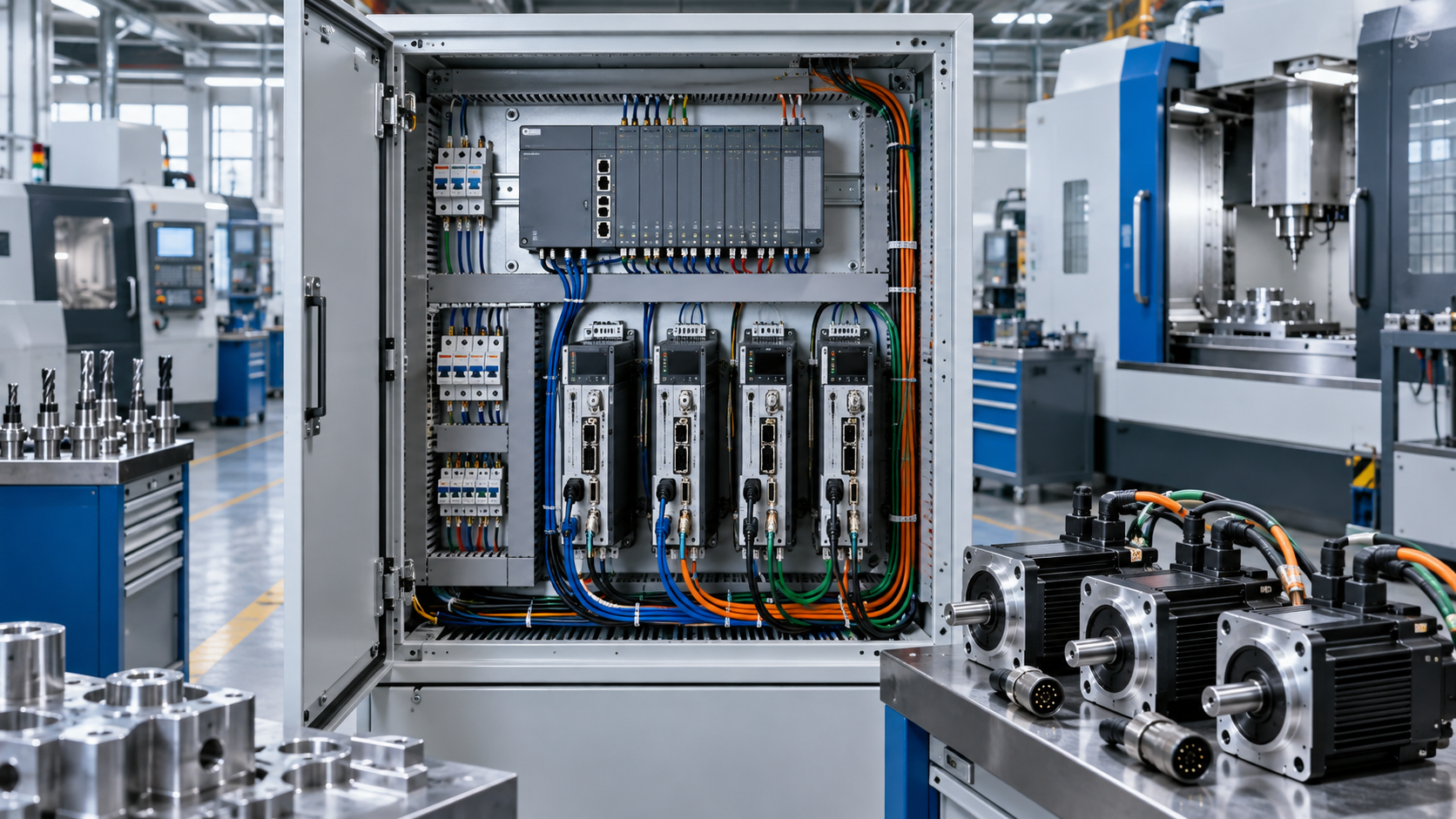
A Mazak CNC retrofit can work with the servo drives already installed, but only when the replacement controller supports their command interface, feedback arrangement, and operating sequence. A drive that runs correctly under the original CNC is not automatically reusable with another controller. Its operation may depend on communications, parameters, or position-loop functions that the new control cannot reproduce.
The strongest case for retaining drives is a documented interface, supported feedback, serviceable hardware, and a clear commissioning procedure. An unidentified serial connection, inaccessible parameters, or missing encoder documentation is a reason to stop short of approving reuse—not a wiring detail to resolve after installation. Compatibility must be established for the complete control chain, not just the drive connector.
Identify the installed system before selecting the replacement control
“Mazak” and the machine model are insufficient to establish servo compatibility. The installed CNC generation, drive configuration, motor type, feedback devices, and previous repairs all matter. A replacement drive fitted during an earlier service intervention can also make the machine different from its original documentation.
Record the full identifiers from the CNC, each axis amplifier, power supply module, motor, and encoder. Include hardware revisions and firmware versions where accessible. Photograph labels and connector designations, and compare them with the electrical drawings. A controller supplier needs this information to confirm support for specific hardware, rather than offering a general statement that its system can retrofit the machine.
Before disconnecting the original control, preserve available CNC parameters, drive parameters, PLC or ladder backups, compensation tables, and reference-position information. Some drives depend on configuration supplied through the original control. A parameter list may therefore be as important as the amplifier itself, especially if a replacement unit later needs commissioning.
Build an axis-by-axis record. Linear axes, rotary axes, and auxiliary positioning mechanisms need not use the same interface. The spindle should be recorded separately: retaining the axis drives does not establish compatibility for spindle orientation, rigid tapping, or turning functions that require synchronized spindle feedback.
The command interface determines whether reuse is practical
The first technical question is how the existing CNC tells the drive to move. Connector shape and pin count cannot answer it. The electrical signal, command meaning, operating mode, and communications protocol must all match the proposed controller.
An analog interface can offer a feasible integration route, but an analog input alone does not prove that a drive is reusable. The input might be intended for a different operating mode or require a separate communication channel to enable normal operation. Confirm its purpose in the relevant manual and parameters.
For a digital link, require confirmation against the exact drive model and supported revision. Physical compatibility with a network connector does not establish protocol compatibility. Even support for the same named network does not necessarily guarantee the required drive profile, synchronization behavior, or parameter access.
A protocol gateway should be treated as an engineered subsystem, not an automatic solution. It must handle command timing, feedback, drive states, faults, and loss of communication predictably. If a supplier proposes one, request evidence that the complete combination supports coordinated machine-tool motion, rather than merely exchanging data with the amplifier.
Determine where the position loop will run
A retrofit changes more than the source of motion commands. It can change which device calculates position error and how that error becomes motor torque. That distinction affects both compatibility and machining performance.
With a velocity-command arrangement, the CNC can close the position loop while the drive handles the inner velocity and current loops. The replacement CNC then needs timely position feedback and suitable tuning functions. With a torque-command arrangement, the controller takes responsibility for additional motion-control functions; it cannot be treated as equivalent to a velocity interface.
With a position-command drive, the drive closes its position loop internally. The CNC must supply coordinated commands through a supported interface and receive the status or feedback required by its control architecture. Encoder routing and tuning responsibilities will therefore differ from those of an analog velocity system.
A machine can jog successfully while still having unacceptable contouring performance. Jogging shows that motion is possible; it does not establish coordinated-axis accuracy, reversal behavior, or following-error control under acceleration and cutting load. The proposed architecture must support the machine’s required performance, not merely make each motor turn.
Trace feedback from the motor to the controller
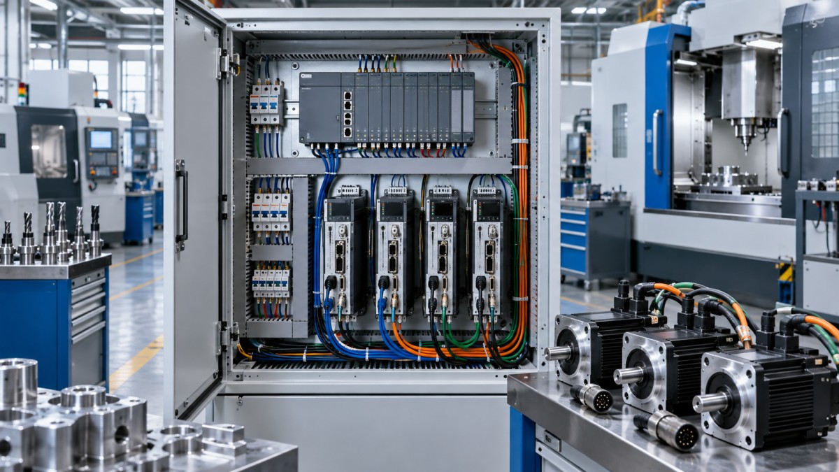
Retaining the original motor and drive can preserve a compatible motor-feedback pair, but the replacement CNC still needs the position information required by its control scheme. Determine whether it will receive feedback directly from an encoder, through an amplifier output, or over a supported digital link.
Encoder compatibility involves more than resolution. Check signal format, supply requirements, electrical levels, index behavior, communication protocol, and whether the device reports incremental or absolute position. A proprietary absolute encoder cannot be assumed to provide a standard incremental output. Likewise, a drive’s feedback output may be scaled or processed rather than an unchanged copy of the motor encoder signal.
Feedback also has different jobs. Motor commutation feedback allows the drive to control the motor correctly; machine-position feedback tells the control where the axis is. One cannot automatically replace the other. If the machine has linear scales or another load-side measuring system, establish whether the proposed CNC can retain that feedback arrangement and support the corresponding loop configuration.
Do not assume an encoder can simply be connected to two receiving devices. Additional loading, grounding paths, or unsuitable signal distribution can degrade reliability. Any feedback sharing requires a documented electrical arrangement, including suitable buffering or isolation where necessary.
Absolute-position recovery deserves explicit attention. Establish what happens after power loss, battery replacement, an encoder alarm, or drive replacement. If the new architecture cannot preserve the original absolute-position behavior, the machine will need an approved referencing procedure and appropriate travel protection. This is especially important where reference positions affect tool changing, rotary-axis limits, or collision avoidance.
Drive enable, faults, and stopping behavior are part of compatibility
The replacement control must reproduce a valid operating sequence: establish readiness, enable the drive under permitted conditions, issue motion commands, monitor faults, and remove motion authority appropriately. “Servo ready” and “servo enabled” are not necessarily interchangeable states. Nor should a reset output clear a fault without resolving its cause.
Document the signals and conditions associated with:
- Drive readiness, enable, alarm indication, and alarm reset.
- Travel limits, reference switches, and permitted recovery movement.
- Motor-brake release and engagement, especially on gravity-loaded axes.
- Contactor control, power-supply readiness, and shared-drive faults.
- Emergency stopping, guarding, and prevention of unexpected restart.
A vertical axis requires particular care. Removing torque can allow movement if the brake sequence or mechanical support is inadequate. Brake control must be coordinated with the ability to hold the axis, and the brake’s intended function must be understood rather than assumed.
A normal CNC stop command is not, by itself, a safety function. The retrofit must preserve or redesign the required protective functions through a machine-specific risk assessment and applicable requirements. Where safe torque off is used, it prevents torque production; it does not by itself provide controlled deceleration or secure a gravity-loaded axis.
These circuits should not be bypassed merely to demonstrate motion. Compatibility testing and commissioning require controlled procedures, qualified personnel, and appropriate isolation when working on electrical equipment.
Check shared power hardware and the condition of retained equipment
Servo amplifiers may share a power supply, DC bus, regenerative equipment, or coordinated fault circuit. Replacing one component can affect the remaining drives. A mixed old-and-new arrangement therefore needs an electrical design review rather than an assumption that each amplifier is independent.
If the plan retains motors but replaces drives, assess that pairing separately. Motor current, voltage, speed, feedback, commutation requirements, thermal protection, and brake control must be supported by the replacement amplifier. A motor’s power rating alone is not enough to select a compatible drive.
Functional compatibility also does not establish remaining service life. Review alarm history, cooling condition, connector damage, contamination, and available diagnostic evidence. Inspect the retained power equipment using appropriate service procedures. An operational drive with intermittent faults or unavailable replacement parts may undermine the purpose of replacing the CNC.
Supportability matters after commissioning. Determine whether parameters can be backed up and restored, whether fault descriptions are available, and whether a replacement drive can be configured without the removed control. A system that works only with its current amplifier and undocumented settings has a substantial maintenance limitation.
Approve reuse against evidence, not the lowest hardware quotation
For a Mazak CNC retrofit, retaining drives is a defensible choice when the exact interface is supported, feedback and loop responsibilities are resolved, protective functions can be maintained, and the hardware remains serviceable. The quotation should identify those conditions explicitly, including any required interface modules, rewiring, parameter changes, and commissioning work.
Replacement becomes more attractive when reuse requires an unsupported communication bridge, unavailable configuration tools, uncertain feedback conversion, or extensive fault-prone adaptation. The relevant comparison is the cost of returning a reliable machine to production—not simply the purchase price of new amplifiers versus keeping the old ones.
Request a written compatibility statement covering the controller, drive revisions, motors, feedback devices, and proposed operating modes. Unresolved dependencies should be identified before removal of the existing CNC. A statement such as “supports analog servos” is not sufficient approval for a particular installed system.
Acceptance criteria should also be agreed before installation. Establish a baseline while the original control still operates, where feasible, separating existing mechanical problems from control-related behavior. Backlash, lubrication faults, damaged bearings, or ballscrew problems will not be corrected merely by changing the controller.
Commissioning should demonstrate correct feedback direction, referencing, limits, fault handling, brake sequencing, and recovery after power interruption. Performance checks should then cover positioning repeatability, coordinated motion, reversals, following error, and representative machining conditions against agreed requirements. Relevant spindle-dependent functions need separate verification.
The decision is not whether the old drives can be made to move. It is whether the proposed controller can operate them accurately, stop them appropriately, diagnose their faults, and support their replacement later. If that chain can be documented and tested, retaining the drives can be a sound retrofit strategy. If it cannot, drive replacement removes a compatibility risk that wiring changes alone will not resolve.
Recommended for You
![]() Mitsubishi Electric Announces Physical AI System Linking Humanoid Robots and CNC MachinesMachine Tool Industry Editorial Team
 Precision Machining for Defense: Supplier Quality and Traceability ChecksManufacturing Market Research Center
![]() Nidec Machine Tool Launches MVR-5X Five-Axis Gantry MachineMachine Tool Industry Editorial Team
 Choosing a Precision Disc Parts Manufacturer in China: Tolerances and Quality ChecksManufacturing Market Research Center
![]() Siemens Executive Says AI Could Raise Factory Automation to 80%Manufacturing Market Research Center
 Choosing Automated Machine Tools for High-Mix, Low-Volume ProductionMachine Tool Industry Editorial Team


Aris Katos
Future of Carbide Coatings
15+ years in precision manufacturing systems. Specialized in high-speed milling and aerospace grade alloy processing.
▶
Choosing a CNC Machine for Mold Making: Accuracy, Rigidity, and Surface FinishCNC Machining Technology Center▶
How to Cut CNC Machining Energy Use per Part Without Longer Cycle TimesCNC Machining Technology Center▶
Will a Mazak CNC retrofit work with your existing servo drives?CNC Machining Technology Center▶
Do energy-efficient machine tools reduce power use at partial load?CNC Machining Technology Center▶
Comparing energy-efficient machine tools by energy use per partCNC Machining Technology Center
▶
Mastering 5-Axis Workholding Strategies
Join our technical panel on Nov 15th to learn about reducing vibrations in thin-wall components.

Providing you with integrated sanding solutions
Before-sales and after-sales services
Comprehensive technical support