• Global CNC market projected to reach $128B by 2028 • New EU trade regulations for precision tooling components • Aerospace deman
NYSE: CNC +1.2%LME: STEEL -0.4%

Shaft Parts: Common Types, Materials, and Industrial Applications
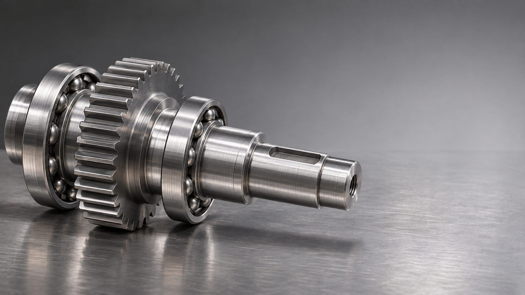
Shaft parts transmit motion and power throughout industrial machinery, from automotive drivetrains to automated production equipment. Their performance depends on design, material selection, manufacturing accuracy, and operating conditions.
The right shaft depends on what it must carry, how it connects to other components, and where it operates. This guide explains the main options and their practical trade-offs.
What Are Shaft Parts, and How Do They Work?
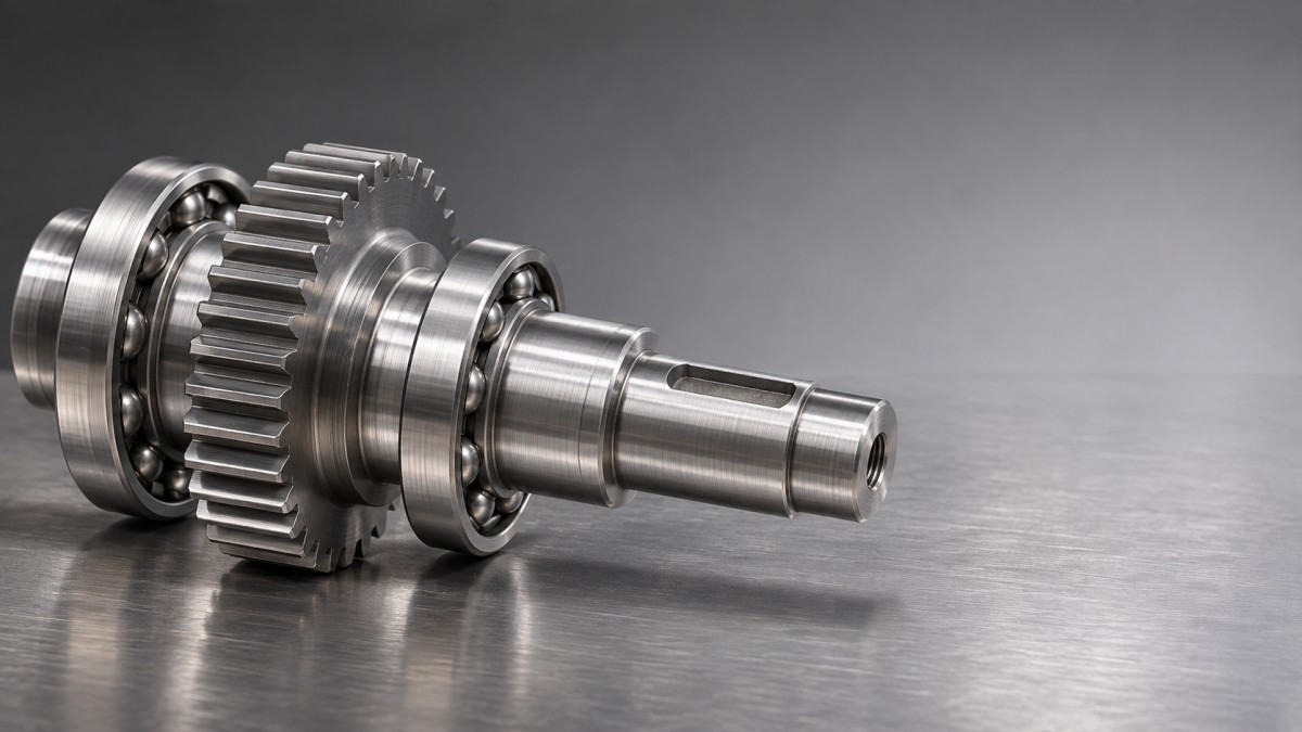
A shaft is a generally cylindrical machine component that supports rotating elements, transmits torque, or both. Bearings, gears, pulleys, and couplings commonly connect to it.
Some shafts carry substantial torque between a motor and a driven load. Others primarily position components or support rotation, with comparatively little torque transmission.
A shaft differs from an axle in its usual function: a shaft typically transmits torque, while an axle generally supports rotating components without transmitting drive torque.
In practice, terminology varies between industries. For example, an automotive axle shaft transmits torque, so the component’s actual function matters more than its name.
Shaft parts often include features such as shoulders, keyways, splines, threads, and bearing journals. These features locate mating components and transfer forces through the assembly.
Failure can interrupt an entire production line, even when the shaft itself is inexpensive. Design choices should therefore account for both component performance and maintenance consequences.
Which Types of Shaft Parts Are Most Common?
Straight shafts have a relatively simple longitudinal form and are widely used in conveyors, motors, pumps, and general machinery. Their specific diameters and features depend on assembly requirements.
A straight shaft may have a constant diameter or several machined sections. Simple geometry can reduce manufacturing complexity, although precision bearing seats still require careful control.
Stepped shafts change diameter along their length. The resulting shoulders locate bearings, gears, and other components, making assembly positioning easier and improving axial support.
However, abrupt diameter changes can concentrate stress. Designers commonly add fillets where space permits and check that mating parts clear the transition radius.
Hollow shafts reduce weight by removing material near the center, where it contributes relatively little to torsional stiffness. They can also provide space for cables or fluids.
Hollow construction may introduce extra machining or inspection requirements. Wall thickness, end connections, and the intended load determine whether the weight saving justifies the added complexity.
Splined shafts use multiple longitudinal teeth to engage a matching component. They can transmit substantial torque and, in some designs, allow axial movement between mating parts.
Keyed shafts use a key seated in matching slots to connect a hub and shaft. They are common and serviceable, but keyways create local stress concentrations.
Crankshafts and camshafts convert or coordinate motion rather than simply transmit rotation. Their complex geometry and timing requirements demand more specialized manufacturing and inspection.
Spindles and precision shafts support controlled rotation in machine tools and other equipment. Runout, bearing fit, balance, and thermal behavior can strongly influence finished product accuracy.
How Do You Choose Between Shaft Materials?
Material selection starts with the actual duty cycle: torque, bending, shock, speed, temperature, and environmental exposure. A stronger material alone cannot compensate for poor geometry or lubrication.
Carbon steels are widely used for general-purpose shafts because they offer useful strength, machinability, and availability. Medium-carbon grades can also be heat treated for higher strength.
For lightly loaded machinery, an appropriately specified carbon steel may provide an economical solution. Final properties depend on the grade, section size, and heat treatment.
Alloy steels, such as 4140 or 4340, are often selected for higher loads, shock, or demanding fatigue service. Their performance still depends on processing and final hardness.
These steels can increase material and machining costs, particularly after hardening. They are most valuable when the application requires their additional strength or hardenability.
Stainless steels offer corrosion resistance for environments involving moisture, chemicals, or cleaning. Austenitic and martensitic grades have different strength, corrosion, and heat-treatment characteristics.
Stainless does not mean immune to corrosion. Chlorides, temperature, surface condition, and cleaning practices can affect performance, so the specific grade must match the environment.
Aluminum alloys reduce weight and machine readily in many conditions. Their lower stiffness and wear resistance can limit their suitability for heavily loaded bearing surfaces.
Titanium alloys provide a high strength-to-weight ratio and corrosion resistance, making them relevant in specialized applications. Their cost and machining demands generally restrict routine use.
For unusual temperatures, aggressive chemicals, or strict weight limits, other alloys and engineered materials may be suitable. Material data and application-specific testing should guide the choice.
What Manufacturing Processes Produce Reliable Shaft Parts?
Most machined shafts begin as bar stock, forgings, or other prepared blanks. The starting form depends on production volume, material utilization, geometry, and required properties.
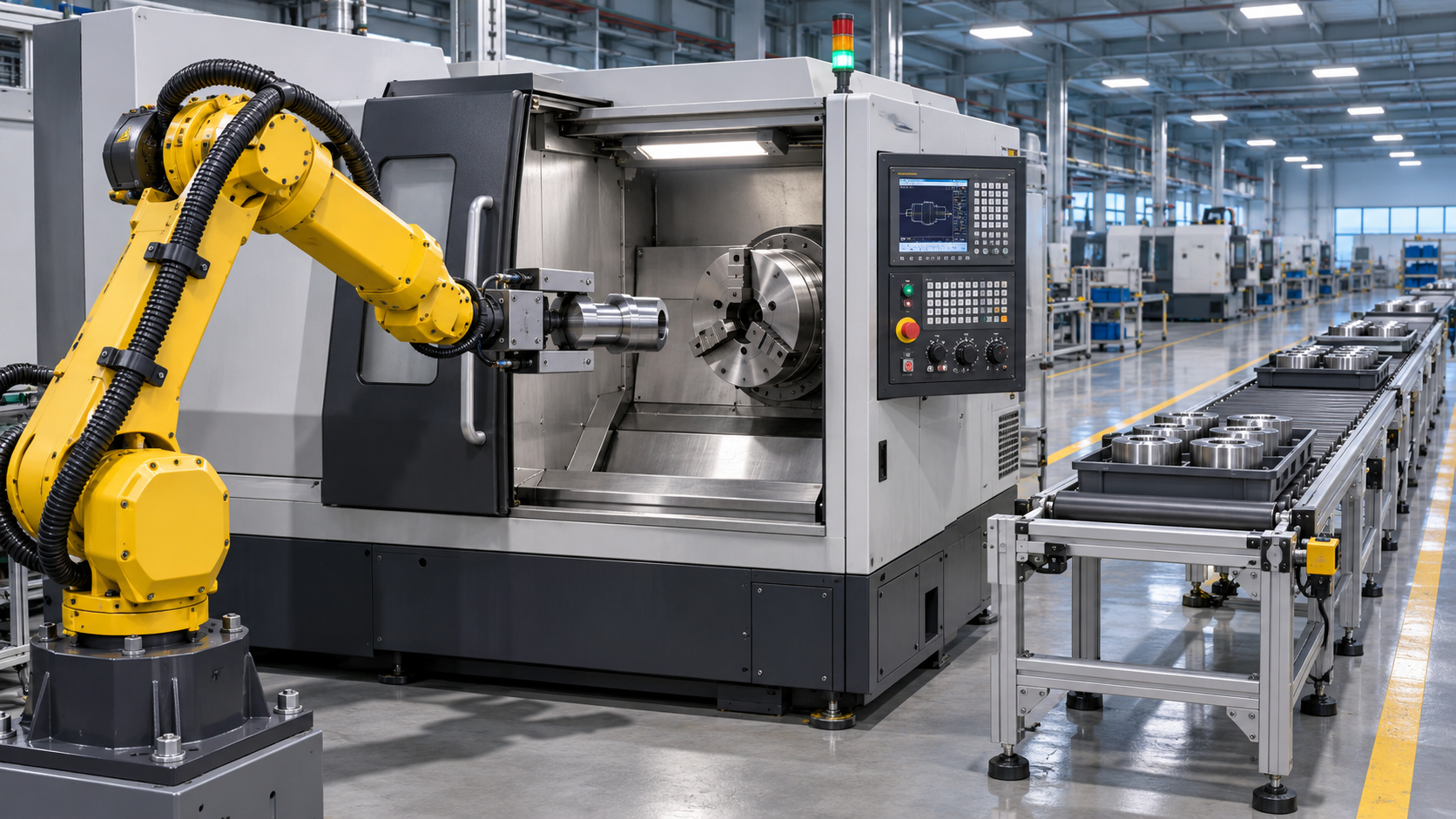
CNC turning creates cylindrical diameters, shoulders, grooves, and many threads by rotating the workpiece against a cutting tool. It is central to producing stepped shafts.
Milling adds features that turning alone cannot easily produce, including flats, keyways, and certain slots. Some multitasking machines combine turning and milling in one setup.
Reducing setups can improve the relationship between features and shorten handling time. The achievable result still depends on machine capability, tooling, workholding, and part geometry.
Grinding can produce precise diameters and surface finishes on bearing journals or hardened components. It is often used after heat treatment when tight control is necessary.
Splines may be milled, hobbed, broached, or formed using another suitable process. The choice depends on spline geometry, material, tolerance, access, and production quantity.
Long, slender shafts need particular attention because cutting forces can cause deflection. Support methods, machining sequence, and finishing allowances help control the final geometry.
For high-volume production, automation can reduce handling variation and support throughput. For prototypes, flexible setups may be more practical than dedicated tooling.
Why Do Heat Treatment and Surface Finish Matter?
Heat treatment changes material properties to suit operating demands. Depending on the steel and process, it can improve strength, hardness, wear resistance, or fatigue performance.
Through-hardening affects a substantial portion of the section, while case-hardening processes create a harder surface over a comparatively tougher core. Neither approach suits every material or application.
Induction hardening can target areas such as journals or wear tracks. Carburizing is used with suitable steels when a hard case and tougher interior are required.
Heat treatment can cause distortion, so the process sequence matters. Manufacturers commonly leave finishing allowance on critical surfaces when subsequent grinding or machining is planned.
Surface finish also affects performance. Rough bearing seats can damage mating surfaces or interfere with fits, while unnecessary polishing adds cost without solving an identified problem.
Specify finish and hardness by functional area rather than applying one demanding requirement everywhere. A seal contact surface, for example, has different needs from an unloaded exterior.
Coatings or other surface treatments may improve corrosion or wear resistance, but they can change dimensions and surface behavior. Their thickness and compatibility must be considered during design.
Which Dimensions and Tolerances Deserve the Most Attention?
A useful drawing identifies the surfaces that locate, support, seal, or transmit torque. These functional relationships matter more than applying uniformly tight tolerances to every dimension.
Diameter and fit determine how a bearing, hub, or seal engages the shaft. The appropriate clearance or interference depends on loading, temperature, assembly method, and component guidance.
Runout describes variation of a surface relative to a specified datum axis during rotation. Excessive runout can contribute to vibration, uneven loading, and reduced machining accuracy.
Straightness and concentric relationships matter especially for long shafts and multi-bearing assemblies. The drawing should state the intended geometric controls and how the part is referenced.
Surface texture affects contact with bearings and seals. A finish suitable for one sealing arrangement may be unsuitable for another, so equipment supplier recommendations are valuable.
Balance becomes increasingly important as rotational speed rises. The required balance quality depends on the complete rotating assembly and its operating conditions, not shaft speed alone.
Inspection methods should match the specification. Micrometers, indicators, coordinate measuring machines, profilometers, and balancing equipment each answer different questions about the finished part.
Tighter tolerances generally increase manufacturing and inspection effort. Reserve the most restrictive requirements for features that demonstrably influence assembly, safety, accuracy, or service life.
Where Are Different Shaft Parts Used?
In automotive drivetrains, transmission shafts, axle shafts, and crankshafts operate under varying torque, fatigue loading, and temperature. Weight, efficiency, and production consistency are important considerations.
In machine tools, spindles and drive shafts support controlled movement and rotation. Bearing arrangements, stiffness, thermal stability, and runout influence machining performance and workpiece quality.
In industrial automation, motor shafts and transmission shafts connect drives to conveyors, actuators, and other equipment. Reliable fits and maintainable connections help reduce unplanned downtime.
In pumps and compressors, shafts transmit power through bearings and seals while exposed to fluid pressure, vibration, or corrosive media. Seal compatibility and deflection deserve particular attention.
In energy equipment, shafts may encounter fluctuating loads, harsh environments, or demanding inspection requirements. Material selection and traceability depend on the specific equipment and applicable standards.
In aerospace systems, weight, fatigue performance, and documented manufacturing controls can be critical. Requirements vary substantially by component and certification context.
In food and pharmaceutical equipment, corrosion resistance and cleanability may guide material and surface choices. Suitability depends on the process, cleaning chemicals, and applicable regulatory requirements.
What Common Shaft Problems Should Readers Recognize?
Fatigue cracking can develop under repeated loading, especially near shoulders, keyways, threads, or surface damage. Good geometry and appropriate surface condition help reduce local stress.
Excessive deflection can misalign gears, bearings, or seals. Increasing diameter, shortening unsupported spans, or changing bearing placement may help, subject to the overall design.
Wear at journals or splines can result from inadequate lubrication, contamination, unsuitable hardness, or movement between mating parts. Replacing the shaft without addressing the cause may repeat the failure.
Corrosion can reduce section strength and create surface pits that promote fatigue. Material choice, protective treatments, drainage, and maintenance all influence exposure.
Vibration may arise from imbalance, misalignment, bent components, bearing problems, or resonance. Diagnosing the whole assembly is more useful than assuming the shaft alone is responsible.
When a failure occurs, preserve evidence such as fracture surfaces and operating records. Qualified analysis can distinguish material defects from overload, installation problems, or changing service conditions.
How Can You Evaluate a Shaft for an Application?
Start by defining the required function: power transmission, component support, precise rotation, or motion conversion. A single shaft may perform several of these roles simultaneously.
Record normal and peak torque, bending loads, rotational speed, operating cycles, temperature, and environmental exposure. Include startup, shutdown, shock, and foreseeable abnormal conditions where relevant.
Next, identify mating components and constraints. Bearing locations, seals, hub connections, available space, and assembly access often determine the practical shaft geometry.
Compare candidate materials and treatments against strength, fatigue, wear, corrosion, weight, availability, and cost. Use verified properties for the intended condition rather than relying on grade names alone.
For a critical application, ask a qualified engineer to assess stresses, deflection, fatigue, and dynamic behavior. Applicable design standards and testing requirements depend on the equipment.
Finally, review manufacturability and inspection with the supplier. A clear drawing, realistic tolerances, material condition, surface requirements, and acceptance criteria make quotations easier to compare.
For replacement parts, confirm dimensions and operating requirements against reliable documentation. A visually similar shaft may have different heat treatment, fits, or load capacity.
Conclusion: Match the Shaft to Its Real Operating Conditions
Shaft parts range from simple straight components to complex spindles and crankshafts. Their value depends on how well geometry, material, manufacturing, and maintenance suit the application.
Start with loads and operating conditions, then evaluate connections, bearing surfaces, tolerances, and likely failure modes. This approach supports a more reliable and cost-effective selection.
When comparing options, focus on the complete assembly and its service life. The best choice balances performance, manufacturability, inspection, and maintenance for the equipment involved.
NEXT ARTICLE
Recommended for You
![]() Perpetua Resources Signs MOU to Evaluate US Tungsten Supply ChainManufacturing Market Research Center
 Choosing an Automated Lathe: Bar Capacity, Accuracy and Production VolumeCNC Machining Technology Center
![]() US Cutting Tool Shipments Reach $287.6 Million in September 2026Machine Tool Industry Editorial Team
 Choosing a Machine Tool Supplier: Service, Lead Times and Total CostManufacturing Market Research Center
![]() India Announces Domestic Five-Axis CNC Machine With 2-Micron AccuracyMachine Tool Industry Editorial Team
 Integrating Industrial Automation into Existing Production Lines: Key StepsMachine Tool Industry Editorial Team


Aris Katos
Future of Carbide Coatings
15+ years in precision manufacturing systems. Specialized in high-speed milling and aerospace grade alloy processing.
▶
Shaft Parts: Common Types, Materials, and Industrial ApplicationsCNC Machining Technology Center▶
Why Heavy Machinery Shafts Fail Under Cyclic Loads and How to Prevent ItCNC Machining Technology Center▶
Shaft Parts for Heavy Machinery: Selecting Materials for High Shock LoadsCNC Machining Technology Center▶
What Is Metal Processing? From Raw Material to Finished Machine PartsCNC Machining Technology Center▶
How long does CNC machine delivery and installation usually take?CNC Machining Technology Center
▶
Mastering 5-Axis Workholding Strategies
Join our technical panel on Nov 15th to learn about reducing vibrations in thin-wall components.

Providing you with integrated sanding solutions
Before-sales and after-sales services
Comprehensive technical support