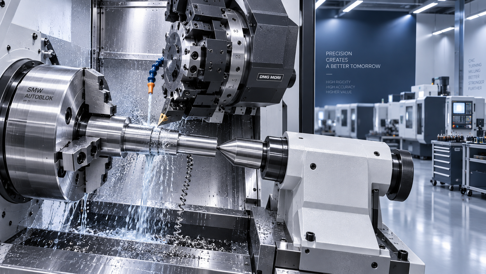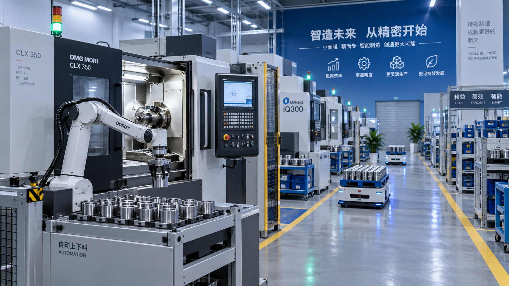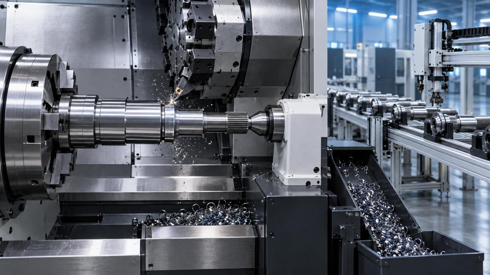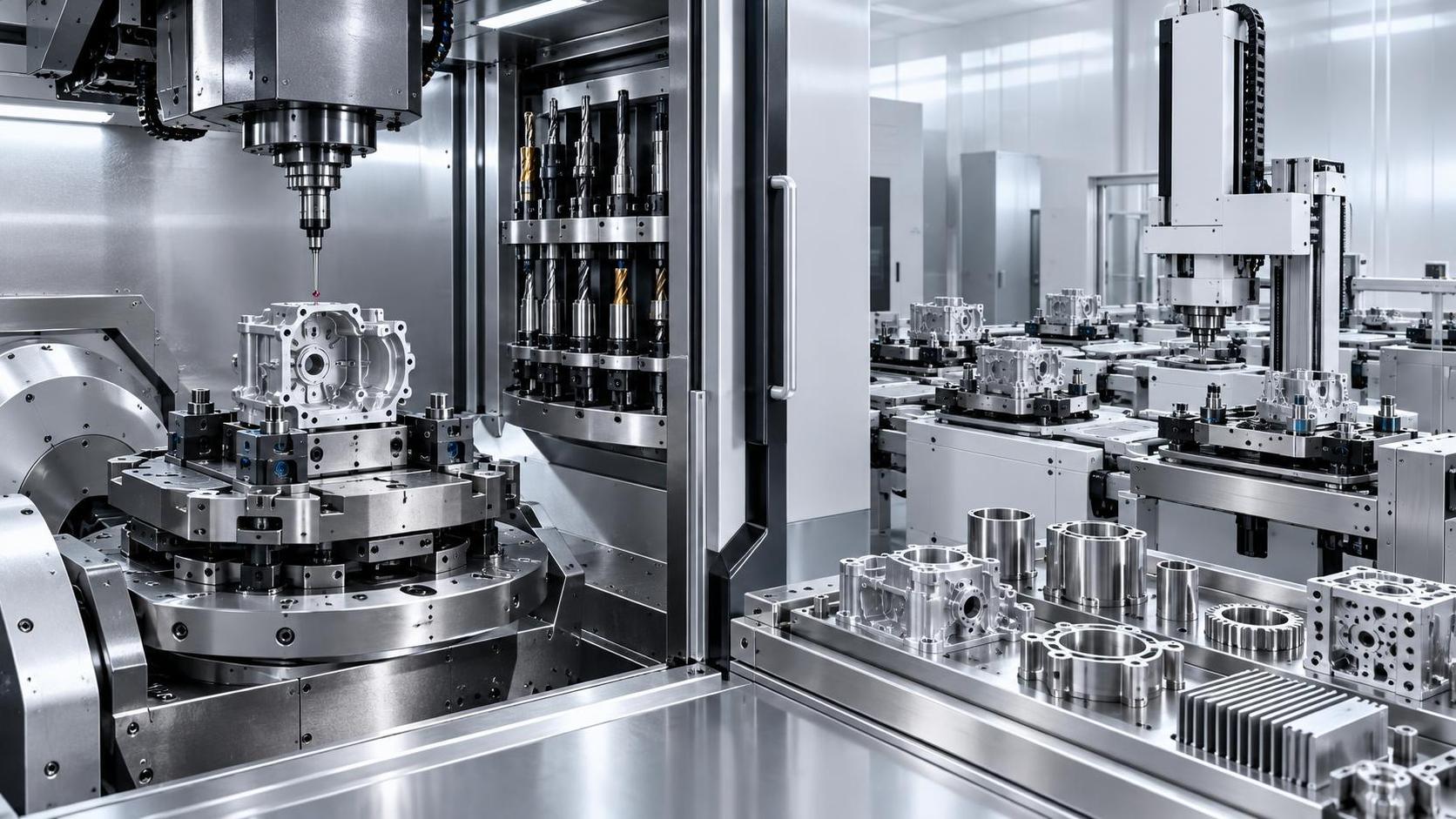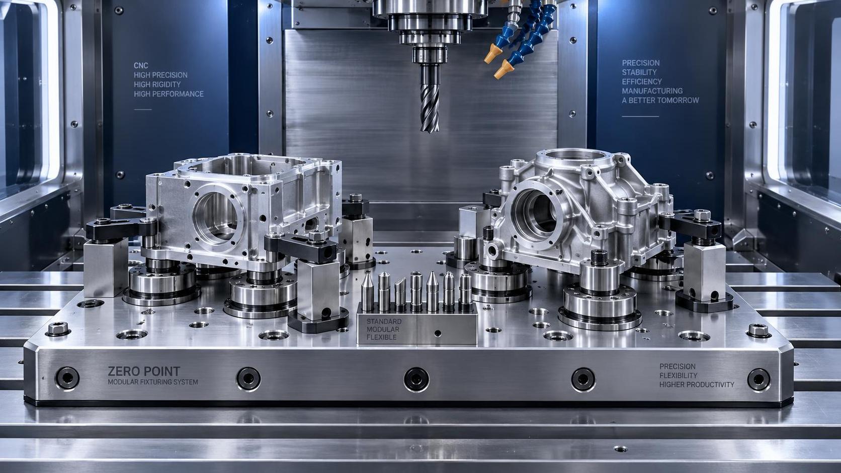
Can one fixture handle multiple part geometries efficiently? In many CNC operations, the answer is yes, but only when flexibility is engineered around repeatability, access, and process control.
Manufacturers facing smaller batch sizes and frequent product changes need to reduce setup time without accepting unstable clamping, excessive inspection, or reduced machining accuracy.
A flexible fixture can improve machine utilization and lower tooling expenditure, yet it is not a universal replacement for dedicated workholding in every high-volume application.
The practical question is not whether one fixture can hold many parts. It is whether it can locate, clamp, and support each part reliably enough for production requirements.
The Short Answer: Flexibility Works Within Defined Limits
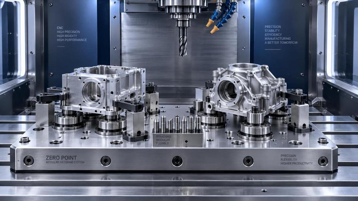
One fixture can handle multiple geometries efficiently when the parts share meaningful reference features, similar loading directions, compatible machining access, and comparable clamping force requirements.
Parts do not need to look identical. They need compatible datum strategies, enough common contact surfaces, and sufficient structural stiffness during the complete machining cycle.
For example, a modular fixture may support several housing variants with shared mounting faces, even when their external profiles, bore locations, and secondary features differ.
However, attempting to accommodate unrelated castings, thin-walled structures, shafts, plates, and irregular forgings on the same base fixture usually creates unnecessary compromise.
Too much flexibility can introduce extra adjustment steps, more operator decisions, and greater risk of incorrect setup. These hidden costs can erase the expected productivity gain.
The strongest flexible fixture concepts standardize the interfaces that matter most: locating datums, mounting patterns, clamp positions, pallet connections, and verification procedures.
In practice, successful multi-geometry fixturing is controlled flexibility. The fixture changes only where the part changes, while stable machine-side references remain consistent.
Start With Part Families, Not Individual Drawings
The first engineering task is grouping parts into realistic families. A part family should be based on manufacturing behavior, not merely product names or customer classifications.
Review shared datum planes, raw material condition, overall dimensions, machining orientation, cutting loads, tolerance requirements, and the number of operations required before grouping components together.
A useful family often has common primary and secondary locating surfaces. These features allow the same base plate, locating pins, or jaw body to remain installed.
For prismatic components, common bottom faces and side datums can support modular locating. For rotational parts, shared bore diameters or center references may enable adaptable mandrels.
Geometry differences become more difficult when they move the center of gravity, block tool access, alter cutting forces, or require completely different support points.
Engineers should also examine the expected product mix. A flexible fixture serving three recurring variants has a clearer business case than one designed for occasional unknown jobs.
Part-family analysis prevents an expensive mistake: designing a highly adjustable fixture for variation that rarely occurs in actual production scheduling.
Locating Accuracy Determines Whether the Concept Is Viable
Clamping holds a workpiece in place, but locating establishes its position. For precision CNC machining, weak datum control is the most common reason flexible fixtures disappoint.
Each component must be constrained according to a deliberate locating strategy, often following the 3-2-1 principle of primary, secondary, and tertiary datum control.
A modular fixture should retain fixed, repeatable machine references while allowing exchangeable locators to match different part dimensions and reference surfaces.
Precision dowel holes, hardened locating pins, zero-point interfaces, and accurately machined base plates reduce variation when fixture modules are removed and reinstalled.
Adjustable elements should not become uncontrolled elements. Every movable stop, locator, or support requires defined position references and a documented locking method.
For demanding tolerances, adjustable hardware alone is rarely sufficient. Use replaceable precision nests, machined adapters, or dedicated locator cartridges for critical dimensions.
The goal is repeatable positioning without lengthy manual indication. If operators must repeatedly probe, tap, and adjust the workpiece, fixture flexibility is not truly efficient.
Clamping Must Match Cutting Forces and Part Stiffness
Different geometries often require different clamping behavior. A thick aluminum housing may tolerate direct hydraulic clamping, while a thin stainless cover may deform under identical force.
Fixture designers should calculate or estimate cutting forces, then compare them with friction capacity, part rigidity, support locations, and the likely direction of machining loads.
Increasing clamp force is not always the solution. Excessive force can distort thin walls, mark finished surfaces, shift soft materials, or create spring-back after release.
Modular clamps should provide controlled force ranges and consistent contact points. Swing clamps, pull clamps, toe clamps, and hydraulic cylinders each suit different access conditions.
Additional supports may be necessary for parts with changing wall thickness or unsupported spans. These supports should resist deflection without over-constraining the component.
When several variants use the same fixture, clamp verification becomes essential. Sensors, pressure monitoring, and clamp-position confirmation reduce the chance of running an incorrect configuration.
Manufacturers should validate the worst-case part, not only the easiest part. The largest, thinnest, least rigid, or highest-force geometry usually exposes fixture weaknesses first.
Tool Access Often Sets the Real Boundary
A fixture may locate a wide range of components successfully, yet still fail because jaws, clamps, supports, or adapters interfere with tool paths.
Before approving a flexible design, programmers should simulate machining for every intended geometry, including roughing, finishing, drilling, probing, tool changes, and chip evacuation.
Fixture elements need clearance from cutting tools, holders, spindle heads, probes, and machine guards. Clearance must be considered throughout every axis movement, not only at final positions.
Five-axis machining adds further complexity because fixture height, clamp reach, and workpiece orientation can limit available rotary travel or cause collision risks.
Low-profile locating and clamping components can improve access, but they must still provide sufficient rigidity. The best design balances reach, force transmission, and collision prevention.
Chip control also matters. Deep pockets around locators can collect chips, causing poor seating and gradual location errors between cycles.
Where chip accumulation is likely, use inclined surfaces, drainage paths, air-blast access, sealed pins, or automated cleaning routines in the production process.
Measure Efficiency Beyond Fixture Purchase Price
The economic value of a multi-geometry fixture depends on total operating cost, not simply the initial price of plates, clamps, locators, or automation interfaces.
Evaluate setup reduction, changeover frequency, machine idle time, fixture storage needs, programming effort, inspection burden, scrap exposure, and maintenance requirements across the expected production mix.
A dedicated fixture may be cheaper for one stable, high-volume component because it can load faster, clamp more simply, and deliver maximum rigidity.
A modular system becomes attractive when product variants change regularly, demand is uncertain, or new parts must enter production without waiting for fully custom tooling.
Managers should calculate the break-even point using realistic annual quantities. Include engineering hours and qualification costs, not only the price quoted by a fixture supplier.
Reduced setup time can create significant capacity without purchasing additional machine tools. This benefit is especially important where skilled setup technicians are limited.
Flexible fixtures also reduce capital tied up in unused dedicated tooling. Their value grows when components have shorter life cycles or customers frequently revise designs.
Standardization Makes Flexible Workholding Repeatable
Flexible fixtures perform best when supported by standardized interfaces. A modular base alone cannot create consistency if every new part requires improvised spacers and undocumented adjustments.
Standardize grid plates, locating-hole patterns, zero-point pallets, clamping hardware, jaw blanks, hydraulic connections, and fixture identification methods wherever practical.
Each approved configuration should have a setup sheet showing locator positions, clamp components, torque or pressure settings, probe routines, and permitted part numbers.
Digital fixture models should be linked to CAM programs and revision-controlled drawings. This prevents a valid machining program from being run with an outdated fixture arrangement.
Quick-change components require error-proofing. Keyed interfaces, asymmetric pin layouts, RFID identification, and visual confirmation can prevent operators from installing the wrong module.
For automated cells, fixture standardization is even more important. Robots, pallet systems, and in-machine probing need predictable workpiece positions every cycle.
A repeatable system reduces dependence on individual operator knowledge. It also makes process transfer easier between shifts, plants, and international manufacturing locations.
Validation Should Be More Than a Single Trial Run
A fixture that works during one sample cycle may still fail in production. Validation should confirm repeatability over multiple loading cycles, operators, and representative machining conditions.
Run capability studies for critical dimensions, particularly features affected by datum transfer, clamping distortion, thermal movement, or module replacement.
Inspect parts before and after unclamping when deformation is a concern. Some materials and thin-wall geometries appear compliant while held, then move after release.
Test repeatability after fixture cleaning, module removal, and reinstallation. These conditions better represent real production than a carefully controlled engineering trial.
Document the allowable variation for each fixture configuration. Operators need clear criteria for replacing pins, servicing clamps, cleaning surfaces, and escalating abnormal results.
In-process probing can provide another layer of control, especially for variable castings or forgings. It should verify key references without replacing sound mechanical location principles.
Validation data gives production teams confidence that one fixture can support multiple geometries without turning every new job into an experimental setup.
When a Dedicated Fixture Is Still the Better Choice
Flexible workholding is not automatically superior. Dedicated fixtures remain appropriate when annual volume is high, cycle time is extremely sensitive, or geometry variation is minimal.
Highly specialized parts may need custom support surfaces, tailored hydraulic circuits, integrated gauging, or orientation features that modular equipment cannot provide economically.
Dedicated tooling can also simplify operator actions. Fewer adjustable components reduce setup mistakes and may support faster loading in automated or tightly balanced production lines.
Safety-critical aerospace, medical, energy, and automotive parts may justify dedicated workholding when risk tolerance is low and validation requirements are extensive.
The decision should therefore be based on variation, volume, tolerance, cycle time, and changeover frequency. It is rarely a simple choice between flexible and fixed tooling.
Many mature facilities use a mixed strategy: modular fixtures for prototypes and medium-volume families, plus dedicated fixtures for proven, stable, high-volume components.
This blended approach preserves responsiveness while protecting throughput where production demand supports specialized tooling investment.
Conclusion: Design Flexibility Around Process Control
Can one fixture handle multiple part geometries efficiently? Yes, when the components belong to a compatible manufacturing family and the fixture preserves dependable locating, clamping, and tool access.
The most successful systems use standardized bases, exchangeable precision modules, documented configurations, and disciplined validation rather than unlimited mechanical adjustability.
Before investing, manufacturers should compare expected setup savings with the risks of lost rigidity, longer loading, complex programming, and increased quality-control requirements.
A flexible fixture should make production simpler for operators and more predictable for quality teams. When it creates uncertainty, a dedicated fixture may deliver better overall value.
Ultimately, efficient multi-geometry fixturing is a manufacturing strategy. It connects part-family planning, CNC programming, workholding engineering, automation, and cost control into one repeatable process.