• Global CNC market projected to reach $128B by 2028 • New EU trade regulations for precision tooling components • Aerospace deman
NYSE: CNC +1.2%LME: STEEL -0.4%

How to Select an Industrial Lathe for High-Volume Shaft Production
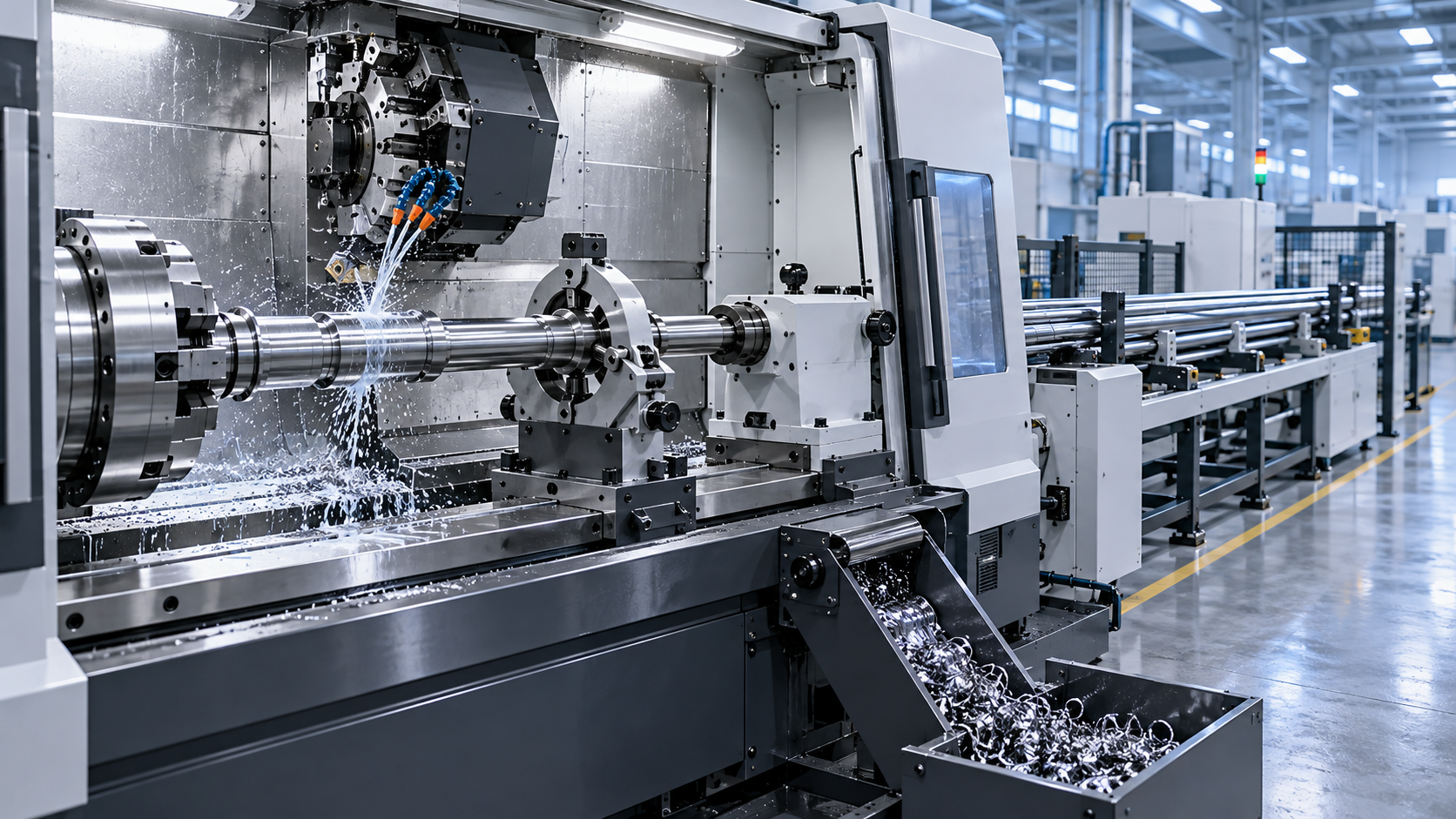
Selecting an industrial lathe for high-volume shaft production is rarely a matter of choosing the machine with the highest spindle speed or the largest bar capacity. The real decision is made at the intersection of part geometry, annual demand, tolerance stability, labor availability, material behavior, and the cost of a stopped line.
For a technical evaluator, the question is not simply, “Can this lathe make the shaft?” Most modern CNC turning equipment can produce a shaft-shaped part. The more valuable question is: “Can this machine hold the required quality through long unattended runs, recover predictably after tool changes, and maintain an acceptable cost per finished part over several years?”
That distinction matters in automotive components, electric motor shafts, hydraulic parts, pump spindles, transmission elements, energy equipment, and other applications where a small variation in runout, diameter, surface finish, or shoulder position can create expensive downstream problems.
Start With the Production Reality, Not the Machine Catalog
Before comparing industrial lathe models, define the actual production envelope. A shaft drawing alone is not enough. Evaluators should gather the full picture: finished dimensions, raw stock form, material grade, annual volume, batch size, target takt time, tolerance bands, inspection requirements, and secondary operations.
A compact stainless-steel shaft with several turned diameters may require a very different machine configuration from a long alloy-steel drive shaft, even if both fit within the same nominal swing diameter. The first may benefit from bar-fed production and live tooling; the second may need a tailstock, steady rest, high torque at lower speeds, and robust control of deflection.
It is also useful to separate “average part” requirements from “worst-case part” requirements. High-volume programs often include several variants. If one long, slender shaft, difficult material, or tight concentricity feature forces repeated compromises, the apparent savings of a smaller machine can disappear quickly.
- What is the maximum finished length, and what is the unsupported length during machining?
- Will stock arrive as bar, forged blank, cut billet, tube, or near-net-shape material?
- Which features must remain concentric after multiple operations?
- Are cross holes, flats, threads, keyways, or milled profiles included?
- How many parts must be produced per shift, including realistic allowance for setup and maintenance?
- Will the machine run attended, lights-out, or within an automated cell?
These inputs turn a broad equipment search into a defensible technical specification.
Rigidity Is the Foundation of Repeatable Shaft Quality
For shaft work, rigidity is not an abstract machine characteristic. It directly affects roundness, taper control, surface finish, tool life, and the ability to remove material without chatter. A lathe that performs well during a brief acceptance demonstration may behave differently after hours of interrupted cuts, thermal changes, and repeated clamping cycles.
Pay close attention to the machine bed design, guideway construction, spindle bearing arrangement, turret structure, and the distance between cutting point and support elements. Box ways may be preferred for heavy interrupted cutting and high damping, while linear guideways can support fast positioning and productive lighter-to-medium turning. Neither approach is universally better; the appropriate choice depends on material removal demands and cycle-time priorities.
Long shafts introduce another layer of risk. Deflection is influenced by workpiece diameter, length-to-diameter ratio, cutting force, clamping method, and support strategy. A tailstock may be sufficient for some parts, but a programmable steady rest or follow rest can be essential when machining slender sections, maintaining cylindrical accuracy, or finishing surfaces that cannot tolerate vibration marks.
Ask the supplier to explain the intended support method for your longest and least rigid component. A credible evaluation includes more than a statement that “a steady rest is available.” It should address whether it can be automatically positioned, whether it integrates with the planned chucking sequence, how it handles diameter variation, and whether its use adds cycle time or manual intervention.
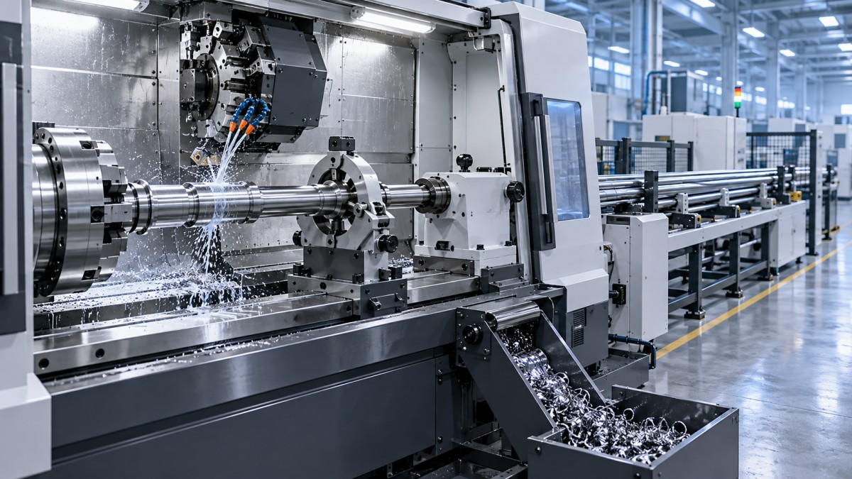
Spindle Performance: Match the Torque Curve to the Material
Spindle speed attracts attention because it is easy to compare. Yet high-volume shaft production often depends more on usable torque, acceleration, deceleration, and thermal behavior than on maximum rpm alone.
When turning larger diameters, machining alloy steels, cutting threads, or performing heavy roughing, torque available at the actual cutting speed is often more important than a high top speed. Conversely, small-diameter shafts in aluminum, brass, or free-machining steel may benefit from rapid acceleration and higher rpm, particularly when short cycles contain frequent spindle starts and stops.
Review the spindle motor curve rather than relying on a headline power figure. Determine whether the machine delivers continuous or short-duration peak power, where constant torque ends, and how the selected chuck, collet system, or bar feeder affects the usable speed range. A machine can be technically capable of reaching a certain rpm while the installed workholding arrangement limits practical operation below that level.
Thermal control deserves equal attention. In a production environment, the machine should reach stable behavior predictably and maintain dimensional consistency across a shift. Consider spindle cooling, hydraulic and coolant heat management, control compensation functions, and the manufacturer’s approach to warm-up routines. For shaft components with tight diameter or location tolerances, thermal drift can be more damaging than an occasional dramatic failure because it quietly pushes parts toward inspection limits.
Workholding Determines More Than Setup Time
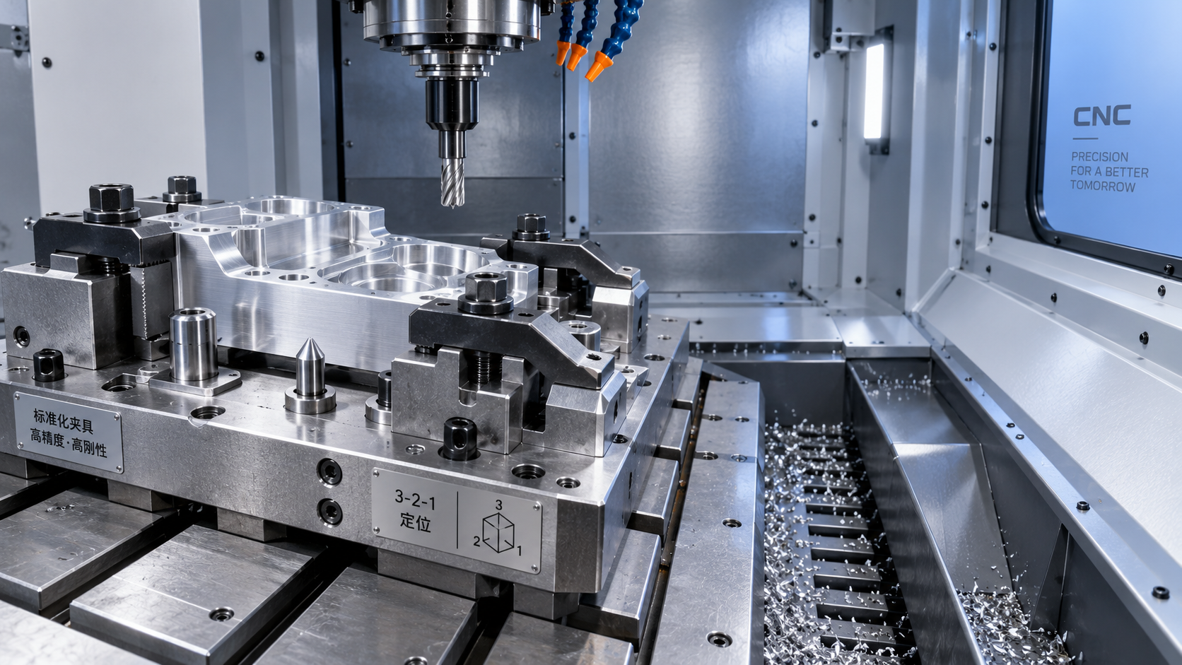
A large share of shaft-production variation begins at the interface between the part and the machine. The choice between a three-jaw chuck, collet chuck, diaphragm chuck, custom soft jaws, expanding mandrel, or between-centers arrangement influences runout, loading consistency, changeover time, and automation feasibility.
For bar-fed parts, collet workholding often supports better concentricity and faster loading than a conventional chuck, especially for smaller diameters. For forged or cut blanks, hydraulic chucking with properly machined soft jaws may offer the grip and flexibility required. Where the finished datum must be protected, machining between centers or using an expanding arbor may be the more reliable route.
Technical evaluators should challenge the assumption that a quoted spindle runout figure represents finished-part runout. The part can be affected by stock straightness, jaw wear, clamping pressure, jaw geometry, bar whip, and the transfer from one setup to another. Review the entire locating scheme, including how the part is presented to the machine, not only the chuck specification.
Questions that expose weak workholding plans
- Can clamping pressure be adjusted and monitored for thin-walled or heat-treated parts?
- How will jaw wear be detected before it affects concentricity?
- Does the workholding method leave enough clearance for tools, probes, and part handling?
- Can the same datum strategy be maintained if production moves to a second machine?
- What happens to cycle time when a bar remnant or blank orientation issue occurs?
Cycle Time Must Be Evaluated as a System
A quoted cutting cycle is only one portion of the true production cycle. In high-volume work, seconds lost to bar advancing, chuck actuation, turret indexing, part transfer, gauging, chip clearing, or manual intervention accumulate quickly. The industrial lathe should be assessed as part of a complete process, not as an isolated cutting platform.
For simpler shafts, a two-axis CNC lathe with a bar feeder may provide the best balance of investment, reliability, and output. If the part includes flats, radial holes, cross-drilled lubrication ports, polygon turning, or milled grooves, a lathe with a C-axis, driven tools, and possibly a Y-axis may consolidate operations and reduce handling. A sub-spindle can finish the reverse side in one cycle, but its value depends on part length, transfer stability, and whether the saved handling time outweighs added machine complexity.
Automation should be judged in the same practical way. Bar feeders are natural choices for long runs from round stock, while gantry loaders, robots, and palletized blank handling are often better suited to forgings and pre-cut material. The best automated cell is not necessarily the one with the most equipment. It is the one that can recover from routine events—empty stock, chip buildup, tool-life alarms, or a misoriented blank—without turning minor interruptions into extended downtime.
Tooling Capacity and Chip Control Often Decide the Real Output
A shaft may seem straightforward until the operation list grows: roughing, finishing, facing, grooving, threading, drilling, boring, chamfering, cutoff, deburring, and in-process measurement. Tool count, turret stations, tool change repeatability, and holder accessibility deserve a detailed review.
Do not assume the nominal number of turret positions equals the usable number of tools. Some stations may be occupied by long drills, boring bars, driven-tool attachments, or probes that restrict adjacent positions. When a part family has frequent design variations, reserve capacity can be more valuable than an aggressively compact tooling layout.
Chip management is equally important, particularly with ductile steels, stainless alloys, and long continuous cuts. Poor chip evacuation can damage finished surfaces, interfere with automated loading, create safety concerns, and force operators to intervene. Examine the coolant delivery method, conveyor design, enclosure flow paths, filtration requirements, and access for clearing an unlikely but inevitable chip nest.
For difficult materials, high-pressure through-tool coolant may improve chip breaking and tool life. It should, however, be specified alongside compatible tooling, filtration, pump capacity, and maintenance planning. Treating it as an optional accessory after the process is set can lead to disappointing results.
Accuracy Should Be Specified Over Time, Not Only at Acceptance
Machine positioning accuracy and repeatability are relevant, but high-volume shaft production needs a broader discussion of capability. The meaningful measure is whether the entire process can maintain critical features across tools, shifts, operators, material lots, and planned maintenance intervals.
Identify the characteristics that truly govern function: journal diameter, shoulder location, total indicated runout, cylindricity, surface roughness, thread quality, and concentricity between turned features. Then determine how each will be controlled. A machine probe may verify a feature before transfer; an automatic gauging station may compensate for finishing-tool wear; a post-process gauge may provide final traceability. Each option has different consequences for cost, cycle time, and response speed.
It is wise to ask for a trial based on a representative part or an agreed process simulation. The trial should include the relevant material and, where possible, the intended workholding and tooling strategy. A short demonstration is not a substitute for a capability study, but it can reveal issues that static specifications hide: vibration at a shoulder, insufficient access for a drill, chips wrapping around the part, or an awkward loading sequence.
Reliability, Service Access, and Digital Integration Belong in the Business Case
In a high-volume line, availability has a financial impact that is hard to recover through marginally faster cutting. Evaluate preventive maintenance access, lubrication systems, spindle and turret serviceability, availability of local technical support, spare-parts lead times, and the clarity of diagnostic tools. The machine builder’s ability to support controls, drives, and automation interfaces is especially important for internationally distributed manufacturing operations.
Digital connectivity can also add practical value. Production monitoring, alarm histories, energy data, tool-life tracking, and remote diagnostics help maintenance and process teams see recurring losses rather than relying on anecdotal reports. Integration should be purposeful, though. A useful connection to manufacturing execution systems or quality records is better than a long list of data points that no one reviews.
A Sensible Evaluation Sequence
Rather than scoring machines solely by purchase price, build a weighted evaluation around the risks that matter to the program. Confirm the process route first, then shortlist machines that fit the part envelope and production target. Compare rigidity, spindle characteristics, workholding concept, automation compatibility, tooling layout, quality-control options, support coverage, and estimated operating burden.
Finally, test the assumptions behind the proposed cycle time. Include loading, inspection, tool changes, chip management, planned maintenance, and realistic operator involvement. This often changes the ranking of two apparently similar machines.
The right industrial lathe for high-volume shaft production is the one that makes quality predictable rather than dependent on constant attention. When the machine, workholding, tooling, automation, and measurement strategy are selected as one manufacturing system, manufacturers gain more than output capacity: they gain a process that can absorb volume growth, part variation, and the everyday pressures of modern production without losing control of the shaft features that matter most.
NEXT ARTICLE
Recommended for You
 How to Select an Industrial Lathe for High-Volume Shaft ProductionMachine Tool Industry Editorial Team
 Selecting Machine Tools for Automotive Parts: Accuracy, Throughput, and AutomationMachine Tool Industry Editorial Team
 Industrial Machining: Selecting Processes for Tight-Tolerance Metal PartsCNC Machining Technology Center
 Manufacturing Technology Trends That Improve Throughput and Quality ControlManufacturing Market Research Center
 How to Design Cost-Effective Fixtures That Maintain Cycle Time in Mass ProductionCNC Machining Technology Center
 Is Learning CNC Programming Worth It for Shop Owners Seeking Higher Margins?CNC Machining Technology Center

Aris Katos
Future of Carbide Coatings
15+ years in precision manufacturing systems. Specialized in high-speed milling and aerospace grade alloy processing.
▶
How to Select an Industrial Lathe for High-Volume Shaft ProductionMachine Tool Industry Editorial Team▶
When Does CNC Turning Pay Off? A Break-Even Guide by Annual Part VolumeMachine Tool Industry Editorial Team▶
How to Compare CNC Metal Lathe Brands ObjectivelyMachine Tool Industry Editorial Team▶
CNC Lathe Quick Installation Guide: How to Avoid Alignment and Wiring MistakesMachine Tool Industry Editorial Team▶
CNC Lathe Quick Installation Guide: Common Setup Mistakes and How to Avoid ThemMachine Tool Industry Editorial Team
Mastering 5-Axis Workholding Strategies
Join our technical panel on Nov 15th to learn about reducing vibrations in thin-wall components.

Providing you with integrated sanding solutions
Before-sales and after-sales services
Comprehensive technical support