• Global CNC market projected to reach $128B by 2028 • New EU trade regulations for precision tooling components • Aerospace deman
NYSE: CNC +1.2%LME: STEEL -0.4%

How to Select a Slant Bed Lathe for High-Precision Shaft and Chuck Work
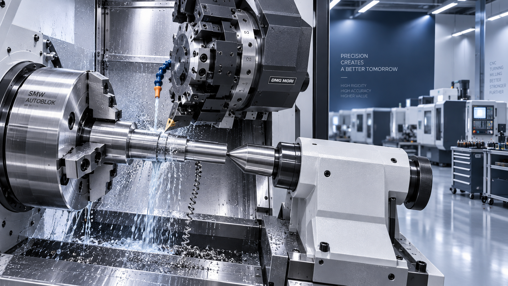
A slant bed lathe is not selected for precision shaft and chuck work by comparing brochure figures in isolation. The machine must preserve geometric accuracy while the workpiece, chuck, turret, tooling, coolant load, and cutting forces change through a production cycle. A lathe with an impressive maximum spindle speed can still be a poor fit if its spindle nose, guideway configuration, thermal behavior, or workholding arrangement does not match the actual parts.
The key selection question is therefore not simply “How accurate is the machine?” It is: can the machine maintain the required diameter, runout, face, and positional tolerances across the intended part family, material range, clamping method, and operating cycle? For high-precision shaft work and chuck-held components, that answer depends on the interaction of structural design, spindle system, axes, workholding, and process control.
Start with the finished part, not the machine envelope
A technically sound evaluation begins with a part matrix rather than a generic machine specification sheet. Separate shaft parts from chuck work because their dominant risks differ.
Long shafts are governed by deflection, support conditions, concentricity between operations, and the stability of turning under changing diameter-to-length ratios. Chuck-held discs, flanges, rings, and short housings place greater emphasis on gripping distortion, jaw repeatability, face runout, chuck overhang, and access for tools or secondary spindles. A machine intended to cover both families must be assessed at both extremes, not at a nominal workpiece size.
For each representative part, define the required finished tolerances, datum scheme, material, stock condition, maximum interrupted cut, machining sequence, and batch pattern. Include conditions that tend to expose machine limitations: thin-walled chuck work, bar-fed shafts, hard turning, heavy roughing followed by fine finishing, and parts requiring transfer from a main spindle to a sub-spindle.
The result should identify the dimensions that actually drive machine capability. These commonly include:
- diameter tolerance and cylindricity on critical journals;
- total indicated runout relative to a functional datum;
- face runout and perpendicularity on chuck-held features;
- concentricity after part reversal or spindle transfer;
- surface finish on bearing seats, seal lands, and precision bores;
- repeatability after thermal warm-up and after tool changes;
- cycle-time stability when roughing and finishing are combined.
Maximum turning diameter and maximum turning length remain necessary checks, but they are only clearance limits. They do not indicate whether the machine will machine a slender shaft without chatter or hold a thin flange without jaw-induced deformation.
Why the slant bed angle matters beyond chip evacuation
The slant bed lathe configuration is valued for gravity-assisted chip flow, good operator access, and a compact relationship between spindle, turret, and guideways. Its real importance in precision work, however, lies in the force path through the structure.
During turning, radial and tangential cutting forces act through the tool, turret, saddle, guideways, and bed. A well-designed slant bed directs these loads into a wide, rigid casting structure while maintaining predictable axis motion. The bed angle alone does not prove rigidity. Two machines with similar slant angles can behave very differently because of bed mass, rib design, casting quality, guideway spacing, turret mounting, and the distance between the cutting point and supporting structures.
Evaluate the complete structural loop: spindle housing to workpiece, workpiece to tool tip, tool tip to turret, turret to carriage, carriage to guideways, and guideways back to the bed. Every compliant interface in that loop can affect roundness, taper, surface finish, and tool life.
For shaft machining, the distance between the tool tip and the nearest guideway support deserves particular attention. A turret positioned with excessive overhang may reduce stability during deep cuts or when using extended boring bars. For chuck work, assess whether a large chuck, jaws, and fixture plate move the center of mass too far from the spindle bearings. The practical consequence is often not a static accuracy issue but a reduction in usable cutting parameters before vibration becomes limiting.
Guideways: select for the process load, not for a presumed hierarchy
Box guideways and linear roller guideways are often presented as competing categories, but neither is automatically the better choice for precision work. The relevant question is whether the guideway system supports the expected force profile and dynamic behavior.
Box guideways provide large contact areas and can offer strong damping and load-carrying capacity. They are frequently appropriate where heavy interrupted cuts, large chuck work, difficult materials, or high cutting loads are integral to the process. Their condition, lubrication design, and alignment quality matter greatly; a box-way machine cannot deliver its expected advantage if stick-slip, uneven wear, or poor lubrication compromises low-feed motion.
Linear roller guideways can provide rapid traverse, low friction, and responsive axis motion. They can be highly effective for precision production, especially when the machine structure, rail size, block preload, and mounting arrangement are engineered for the application. Their limits emerge when evaluators assume that high acceleration is equivalent to high cutting stability. On demanding roughing cuts or severe interrupted turning, the guideway system must be considered together with the carriage mass and damping characteristics.
For fine finishing, request evidence relevant to low-speed axis behavior: fine interpolation capability, reversal performance, servo stability, and the machine’s ability to feed smoothly at the rates required for finishing. A published positioning resolution is not a substitute for controlled movement under cutting load.
Spindle selection is a bearing, nose, and thermal decision
Spindle speed is often overemphasized. High speed is useful for small diameters, aluminum alloys, and certain finishing operations, but the spindle must also provide adequate torque at the cutting range used for the intended materials. For precision shaft and chuck work, a better starting point is the spindle duty profile: workpiece mass, chuck or collet size, cutting speed range, anticipated interrupted cuts, and required continuous operating time.
The spindle nose standard and size affect more than chuck compatibility. They determine the stiffness of the workholding interface and influence the practical limits of fixture overhang. A larger spindle nose may improve support for heavy chucks and fixtures, while a smaller configuration may be more suitable for compact, high-speed precision parts. The correct choice follows the part family; oversizing can introduce inertia and access penalties, while undersizing can reduce stability and clamping flexibility.
For high-precision chuck work, assess radial and axial runout at the actual workholding interface, not only at a bare spindle test point. A spindle can meet a tight no-load runout specification while the combined chuck, jaw, and workpiece system introduces a materially larger error. If production depends on soft jaws, the repeatability of the chuck and the quality of jaw boring procedures become part of the accuracy system.
Thermal behavior is equally important. Heat comes from spindle bearings, motor losses, belt or gear transmission, hydraulic equipment, coolant, and repeated acceleration. It changes spindle growth and can shift the relative position between spindle centerline and turret. Features such as spindle cooling, controlled lubrication, thermal compensation, and stable machine warm-up procedures should be examined as a system. Compensation can correct predictable drift; it cannot fully correct unstable thermal conditions caused by inconsistent duty cycles, shop temperatures, or heat accumulation in workholding.
Workholding determines whether nominal machine accuracy reaches the part
Many precision turning issues originate at the chuck rather than in the lathe. The evaluation must establish how the workpiece will be located, gripped, supported, and transferred through every operation.
Three-jaw power chucks provide flexibility, but their repeatability depends on scroll condition, jaw stroke position, clamping force, lubrication, and the relationship between jaw geometry and the part diameter. For tight runout requirements, bored soft jaws, pie jaws, collets, mandrels, or purpose-designed fixtures may be more appropriate than relying on standard hard jaws. The selected slant bed lathe should have the hydraulic capacity, drawtube arrangement, guarding, and spindle clearance needed for the intended system.
Thin-walled parts require a separate evaluation of clamping distortion. A chuck can indicate acceptably before cutting, yet release a part that changes form once jaw force is removed. This is not solved by selecting a more accurate machine. It requires control of clamping pressure, jaw contact geometry, machining sequence, and, in some cases, expanding mandrels or internal support methods.
For shafts, determine when tailstock support is sufficient and when a programmable steady rest is necessary. Tailstock quill stiffness, center type, thrust control, and alignment affect taper and surface quality. A tailstock is not merely an accessory; it is part of the machining structure for long parts. If shafts require turning close to the supported end, inspect turret interference and the achievable tool approach. If the process includes center drilling, turning between centers, and subsequent chuck operations, datum retention between stages needs explicit planning.
Turret, tools, and axis arrangement must support the tolerance chain
A rigid turret with repeatable indexing is fundamental, but tool interface choices can materially affect results. Boring bars, parting tools, driven tools, and long toolholders create different load conditions. Verify the available station types, tool shank capacity, live-tool torque where applicable, and clearance around the chuck and tailstock.
For tight diameter control, the important issue is not only X-axis positioning accuracy. Tool-tip consistency depends on turret indexing, holder seating, insert geometry, tool wear behavior, and the control’s compensation workflow. Machines used for families of close-tolerance components benefit from tooling arrangements that minimize reset variation between jobs.
Y-axis capability should not be assumed necessary simply because it is available. It adds value when eccentric drilling, off-center milling, keyway features, or balanced mill-turn operations are required. For purely turned shafts and discs, a simpler two-axis configuration may offer a more direct structural and maintenance case. Conversely, omitting Y-axis capability can force a second setup for features that could otherwise be completed in one clamping, creating a larger concentricity risk than the additional machine complexity.
A sub-spindle should be justified by the part routing. It can reduce handling and preserve datum relationships in complete machining, but its benefit depends on transfer repeatability, synchronization performance, available grip length, and the ability to finish the back side without compromising access or rigidity. Parts with limited gripping land may require dedicated transfer fixtures or a different process concept.
Accuracy specifications need to be translated into acceptance conditions
Catalog claims such as positioning accuracy, repeatability, spindle runout, and circular interpolation accuracy are useful screening data. They are not a complete acceptance basis for a precision application. Values may be stated under controlled conditions, with specific measurement methods, at a particular machine location, and without production workholding or cutting load.
An effective technical specification defines acceptance around the intended process. This can include a test coupon or representative geometry, identified material, defined tooling, machine warm-up state, inspection method, and limits for the features that matter. For example, a shaft test may include a critical journal, shoulder, and bored feature to assess diameter consistency, taper, roundness, and axial relationship. A chuck-work test may include face turning, boring, and a re-clamped feature to reveal the combined effect of spindle, chuck, jaws, and axis behavior.
Where standards are referenced, the measurement method and acceptance scope should be stated clearly rather than relying on a standard number alone. ISO 230 series standards cover several machine-tool test methods, but a compliance statement does not eliminate the need to define the production-relevant test condition.
Automation compatibility should be judged by recovery, not only loading speed
Bar feeders, gantry loaders, robots, part catchers, automatic doors, and in-process gauging can improve unattended operation, but they also add interfaces that can influence precision. A bar-fed shaft process requires attention to bar straightness, guide channel support, remnant handling, spindle liner selection, and vibration at speed. A robotic chuck-loading process must control part orientation, seating confirmation, jaw clearance, and recovery after a misload.
For precision parts, automation evaluation should include what happens after an interruption: tool breakage, low air pressure, a probe alarm, jaw-position mismatch, part-present sensor fault, or an out-of-tolerance measurement. The relevant requirement is not merely that the machine can run automatically, but that it can return to a controlled state without silently producing suspect parts.
In-process gauging can be valuable for thermal drift and tool-wear correction, especially on critical diameters. Its usefulness depends on gauge repeatability, cleanliness, calibration discipline, and the control logic used to apply offsets. A measurement system that reacts to chips, coolant residue, or unstable part temperature can create corrective errors instead of preventing them.
Evaluate maintainability as an accuracy-retention issue
High initial accuracy does not guarantee sustained accuracy. Lubrication accessibility, coolant management, chip evacuation, hydraulic cleanliness, spindle service support, and calibration procedures all influence how well a slant bed lathe retains its performance.
Chip control deserves particular scrutiny with stringy materials, deep boring, and high-pressure coolant. Chips that accumulate around the turret, tailstock, chuck, or probing equipment can damage surfaces, obstruct seating, and interfere with automated handling. Confirm the coolant flow path, conveyor suitability, filtration arrangement, and access for cleaning. A machine that is difficult to clean consistently may be unsuitable for a process with demanding surface or runout requirements.
Service documentation should identify the machine geometry checks that can be performed after installation and during periodic maintenance. Availability of spare parts and local technical support is commercially important, but it is also a technical risk factor when the machine relies on specialized spindle, drive, hydraulic, or control components.
A disciplined selection decision
The best-fit slant bed lathe is the one whose usable performance envelope matches the actual part and process envelope. For long shafts, prioritize the stiffness of the spindle-to-tailstock system, guideway support, steady-rest integration, and control of deflection. For precision chuck work, give equal weight to spindle nose stiffness, chuck and jaw repeatability, fixture overhang, clamping distortion, and access for complete machining.
Machine geometry, workholding, tooling, thermal control, and automation should be reviewed as one tolerance chain. If any link is evaluated separately from the others, nominal machine capability can be mistaken for finished-part capability. A selection based on representative process conditions, clearly defined acceptance tests, and realistic maintenance assumptions provides a much stronger basis than one based on speed, swing, or a single accuracy figure alone.
NEXT ARTICLE
Recommended for You
 How to Select a Slant Bed Lathe for High-Precision Shaft and Chuck WorkCNC Machining Technology Center
 Smart Manufacturing for Small Businesses: Where Automation Delivers the Fastest ROIMachine Tool Industry Editorial Team
 How to Specify a CNC Lathe for High-Volume Automotive Shaft ProductionCNC Machining Technology Center
 How Automated Precision Machining Maintains Tolerance in High-Mix ProductionCNC Machining Technology Center
 How to Evaluate a Machine Tool Factory Before Sourcing CNC EquipmentGlobal Machine Tool Trade Research Center
 CNC Programming Explained: From CAD Models to Reliable Shop-Floor ToolpathsCNC Machining Technology Center





Aris Katos
Future of Carbide Coatings
15+ years in precision manufacturing systems. Specialized in high-speed milling and aerospace grade alloy processing.
▶
How to Select a Slant Bed Lathe for High-Precision Shaft and Chuck WorkCNC Machining Technology Center▶
How to Specify a CNC Lathe for High-Volume Automotive Shaft ProductionCNC Machining Technology Center▶
CNC Turning Explained: How It Works, Key Tolerances, and Best-Fit Part TypesCNC Machining Technology Center▶
Metal Lathe vs CNC Lathe: Which Is Better for Tolerance, Output, and Cost?CNC Machining Technology Center▶
CNC Lathe for Mass Production: What Cycle Time, Bar Capacity, and Automation Features Matter?CNC Machining Technology Center
Mastering 5-Axis Workholding Strategies
Join our technical panel on Nov 15th to learn about reducing vibrations in thin-wall components.

Providing you with integrated sanding solutions
Before-sales and after-sales services
Comprehensive technical support