• Global CNC market projected to reach $128B by 2028 • New EU trade regulations for precision tooling components • Aerospace deman
NYSE: CNC +1.2%LME: STEEL -0.4%

How to Specify a CNC Lathe for High-Volume Automotive Shaft Production
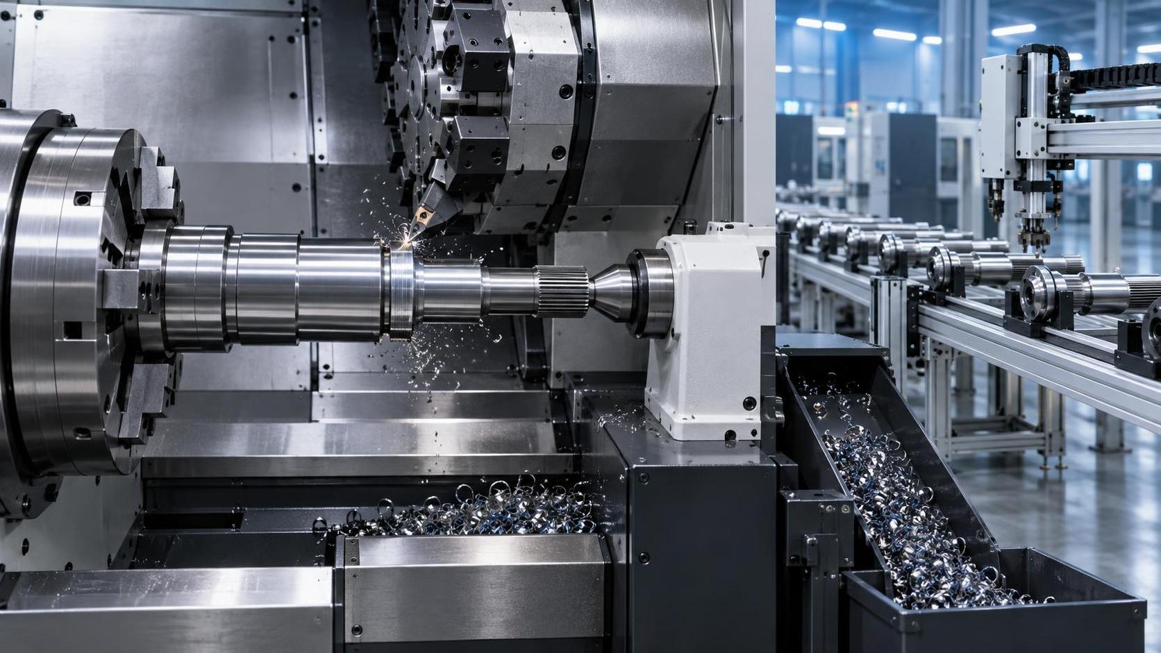
A high-volume shaft program should start with the finished-part process, not the machine brochure. Define every turned feature, the datum chain, material condition, annual mix, takt requirement, and downstream operation before selecting spindle power or axis travel. A lathe that produces a capable first-off part may still be unsuitable when bar variation, tool wear, loading interruptions, chip accumulation, and thermal movement occur through an extended unattended run.
For automotive shafts, the specification must connect machine capability to the features that govern function: bearing seats, seal journals, spline-preparation diameters, threads, shoulders, snap-ring grooves, center features, and runout relationships between them. The right CNC Lathe for Automotive Manufacturing is the one that maintains those relationships at the required output rate with a stable, recoverable process.
Build the machine specification from the shaft family
Start by separating the component family into meaningful groups. A short transmission shaft blank, a long steering-related shaft, and a hardened gear-adjacent shaft may all appear to be turning work, yet they place very different demands on the machine. Length-to-diameter ratio, raw-stock form, interrupted cuts, required concentricity, and whether secondary milling or drilling is needed will change the preferred configuration.
Part drawings alone are insufficient. Review the routing and identify what is truly done on the lathe. A turned shaft may arrive as a forged blank with scale, a saw-cut tube with variable end condition, or a cold-drawn bar. Forging flash, stock allowance variation, eccentric raw material, and uneven saw faces alter the clamping and roughing strategy. A machine selected around nominal finished dimensions can lack the chuck capacity, boring-bar clearance, or torque reserve needed to absorb real incoming variation.
For each shaft family, establish the following process inputs:
- Maximum and minimum blank diameter, including forged or cut-stock condition rather than only the finished outside diameter.
- Overall length, unsupported length during machining, and the location of precision journals relative to the clamping points.
- Material grade, hardness range, surface condition, and any heat treatment performed before or after turning.
- Features requiring a single setup, such as a bearing seat and a locating shoulder whose axial and radial relationship affects assembly.
- Operations that create unfavorable cutting loads, including broad facing cuts, deep grooves, interrupted surfaces, cross holes, or off-center material removal.
- Expected changeover frequency. A dedicated shaft line and a mixed-family cell should not be specified with the same tooling and fixturing assumptions.
These inputs reveal whether a conventional two-axis lathe is enough, whether a subspindle removes a second operation, or whether live tooling and a Y axis are justified. Extra axes are valuable when they eliminate a handling step or preserve a datum relationship. They add little value when every non-turning feature is already produced more reliably in a separate, established operation.
Cycle time must include the events between cuts
Quoted cutting cycle time often excludes the losses that determine output: part loading, chuck actuation, bar feed advance, probing, tool indexing, chip clearing, transfer to a subspindle, part ejection, and recovery after a fault. For a high-volume line, estimate the complete recurring cycle rather than comparing rapid-traverse rates or spindle maximum speed in isolation.
Spindle speed matters only within the usable torque and power range for the workpiece material and cutting diameter. A shaft may begin with large-diameter rough turning that needs torque at modest speed, then finish a smaller journal at a higher surface speed. A catalog peak speed cannot show whether the spindle sustains the required cutting condition through both stages. Request a power-torque curve and examine the continuous operating region, not simply the maximum rating.
Acceleration and deceleration deserve the same scrutiny. Short shafts with several facing, grooving, drilling, and threading operations can spend substantial time changing speed and direction. Fast acceleration improves cycle time only when the chuck, workholding, and part balance permit it without excessive vibration. On a heavier forged blank, a more aggressive spindle response may increase clamping demand and aggravate chatter rather than improve usable throughput.
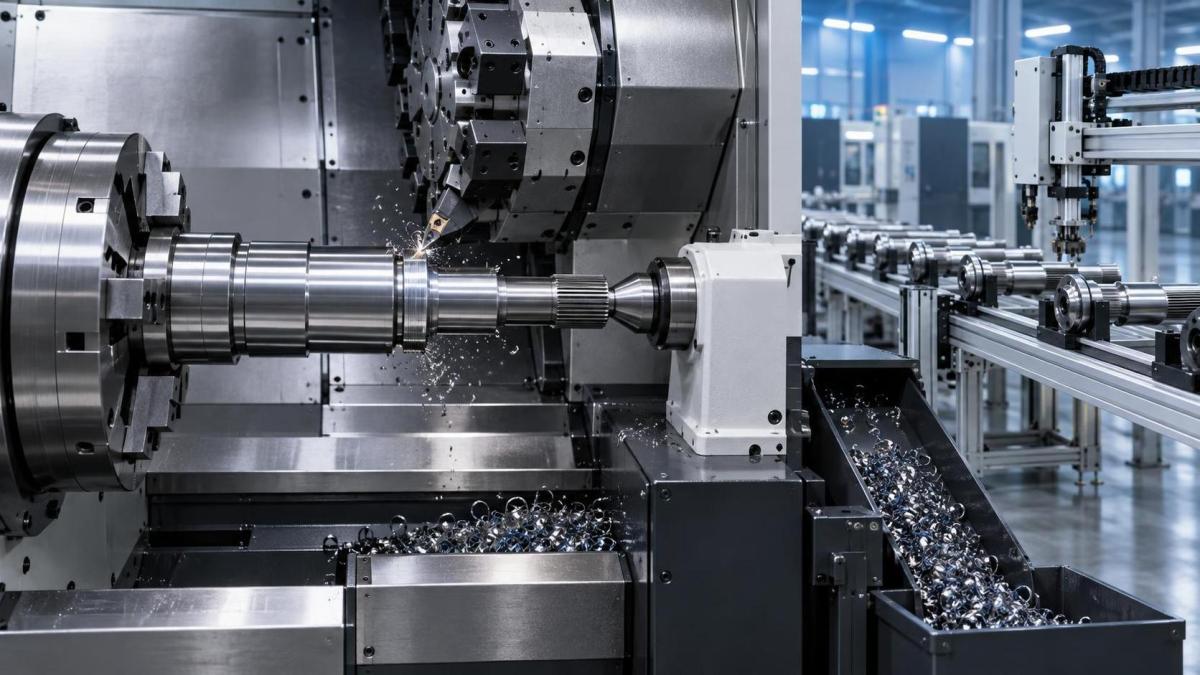
Turret index time is relevant when the process uses many tools, but tool layout is more revealing than the published index figure. A process that repeatedly indexes between adjacent roughing, finishing, grooving, drilling, and cutoff stations has a different loss profile from one that returns across the turret after every feature. Map the actual operation sequence before deciding whether a larger turret, a second turret, or a more compact tool arrangement is warranted.
Control deflection before chasing accuracy specifications
Machine positioning accuracy and repeatability are important, yet they do not directly equal shaft accuracy under load. A bearing journal can drift because of tool deflection, workpiece deflection, jaw distortion, spindle thermal growth, or stock variation even when axis feedback is highly repeatable. The selection review should distinguish geometric machine performance from process capability under the intended cutting forces.
A long, slender shaft is especially sensitive to support strategy. Tailstock capacity should be evaluated for thrust, quill travel, center type, programmability, and repeatable centerline relationship to the spindle. A tailstock that is adequate for light finishing may not provide the stability needed for roughing a long blank. Steady rests and follower rests introduce their own requirements: sufficient access for the tool path, reliable opening and closing sequence, protection against chip intrusion, and surfaces on the part that are suitable for support.
Consider the sequence carefully when a journal will later be used by a steady rest. If that journal is roughed under unstable conditions, then used as a support surface before final finishing, the support can transmit its error into subsequent features. A process may need a preliminary stabilizing diameter, a different clamping direction, or a finish sequence that keeps function-critical journals in the same final setup.
Specify workholding as part of the machine package
Workholding is often treated as an accessory decision, but it determines concentricity, distortion, loading reliability, and access to the part. The chuck must be sized for the actual blank and gripping length, while retaining enough drawbar force for the most demanding cut. More clamping force is not automatically better. Thin-wall shafts, tubes, and finished bearing surfaces can distort under excessive jaw load, creating a part that measures correctly while clamped and moves after release.
Soft jaws should be designed around datum control, not only holding force. Where a critical outside diameter cannot be gripped without damage, collets, expanding mandrels, or specially contoured jaws may be more appropriate. Their selection needs to account for loading tolerance, contamination sensitivity, maintenance access, and how quickly the locating surfaces wear. A highly precise fixture with poor chip tolerance can become the source of intermittent runout in unattended production.
For bar-fed work, verify spindle bore, drawtube capacity, bar feeder compatibility, remnant length, and support for the intended stock shape. A nominal bar capacity says little about practical performance with bent bar, heavy stock, hex material, or tube. For chuck-loaded forgings, specify the interface between the loading device and chuck jaw geometry early. Gripper clearance, orientation control, seating confirmation, and safe transfer of oily or scaled blanks are all part of the achievable cycle.
Tooling capacity should match the wear-management strategy
High-volume turning needs enough stations for productive cutting tools, backup tools where required, probing, and process-specific equipment without forcing poor tool orientation. Count physical stations, but also review available turning positions, driven-tool positions, clearance around the tailstock or subspindle, and allowable toolholder mass. A turret with a large stated capacity can be restrictive if several positions cannot carry the holders needed for deep boring, long grooving, or close shoulder access.
Tool life should be considered as a controlled production event. If a finish insert is changed frequently relative to the planned unattended interval, the machine must support predictable offset management and uncomplicated restart. Sister-tool arrangements are useful only when the replacement tool has been qualified, measured, and positioned so that the handoff does not create a diameter step or surface change. The same principle applies to drills, grooving inserts, and cutoff tools.
Coolant delivery is closely tied to tool life and chip behavior. Through-tool coolant can be important for deep drilling and certain grooving operations, but pressure alone does not solve a poorly directed flow path. Inspect whether the toolholder, turret plumbing, enclosure, and chip conveyor work together to remove long stringy chips from the cut. Automotive shaft materials and geometries can produce chips that wrap around the part, interfere with a part catcher, or prevent full jaw seating on the next cycle.
Automation integration needs defined mechanical and control interfaces
Automation is reliable when the lathe, fixture, loading equipment, gauging, and part discharge are specified as one sequence. The machine enclosure must provide usable access, not merely a nominal opening. Confirm robot reach, gripper approach angle, clearance around an extended tailstock, and the path of a finished shaft into a conveyor, chute, tray, or gauging station. Long parts are prone to swinging or catching during transfer, especially when they leave the chuck with residual coolant or chips.
Part-presence sensing should distinguish between a blank present in the chuck and a blank seated correctly against its datum. These are different conditions. A process that only confirms presence can continue after a chip or burr prevents axial seating, producing a run of parts with shifted shoulder locations. The required sensing approach depends on the fixture and part geometry, but the failure mode should be addressed during cell design rather than after installation.
Specify the signals needed for cycle start permission, load completion, machine ready, alarm classification, part complete, tool-life warning, and controlled recovery. A generic automation handshake may run the cell, yet it can make fault recovery slow when a part is partly machined or retained in a subspindle. Clear state definitions reduce ambiguity after an interrupted cycle and prevent an automatic loader from acting while the machine is in an unsafe condition.
Measure process stability, not only finished samples
For critical journals and axial locations, decide which features need in-cycle probing, post-process gauging, or periodic manual verification. Probing can detect a missing part, verify stock position, and support controlled compensation, but it should not be used to conceal an unstable cutting process. Repeated compensation for a steadily moving diameter may indicate tool wear, coolant-temperature change, inadequate warm-up control, or a fixture problem that requires correction at the source.
Thermal behavior deserves a defined acceptance approach. Spindle growth, ball-screw warming, hydraulic temperature, and coolant temperature affect dimensions differently. A machine can appear stable after it has reached operating temperature while producing a different result during the first production period after a stop. Require a trial that includes warm-up, normal cutting load, tool changes, and sustained automatic cycling. A short demonstration cut cannot reveal whether the machine settles predictably.
Data collection is most useful when it records actionable conditions: alarm history, spindle load trends, tool-life state, probe results, cycle interruptions, and key compensation changes. Collecting every available signal creates noise unless the data is tied to a response rule. For example, an increase in cutoff load combined with more frequent chip-conveyor alarms points toward a chip-control investigation, whereas a diameter drift without load change points more directly toward thermal or measurement causes.
Turn acceptance criteria into a production-representative trial
Acceptance should use representative blanks, approved tooling concepts, intended workholding, and a cycle close to the planned production sequence. The objective is not a single favorable part. Evaluate repeatability across multiple cycles, behavior after tool indexing, stability of critical dimensions after unclamping, chip removal, automatic load and unload actions, and recovery from realistic interruptions.
Ask for evidence of axis geometry, spindle condition, turret repeatability, and safety functions, but keep the trial focused on the shaft process. A machine may meet general inspection values and still struggle with a particular long-reach groove, aggressive roughing pass, or bar-fed cutoff operation. Conversely, a machine with modest headline specifications may deliver a more stable result when its support arrangement, workholding, thermal behavior, and automation interface suit the part family.
The final specification should therefore state the part envelope, material range, process sequence, required support equipment, workholding concept, tooling layout, automation interfaces, measurement method, chip-management arrangement, and acceptance conditions together. That level of definition exposes missing assumptions before purchase and makes the installed lathe far more likely to sustain the intended shaft process rather than merely demonstrate it.
NEXT ARTICLE
Recommended for You
 How to Specify a CNC Lathe for High-Volume Automotive Shaft ProductionCNC Machining Technology Center
 How Automated Precision Machining Maintains Tolerance in High-Mix ProductionCNC Machining Technology Center
 How to Evaluate a Machine Tool Factory Before Sourcing CNC EquipmentGlobal Machine Tool Trade Research Center
 CNC Programming Explained: From CAD Models to Reliable Shop-Floor ToolpathsCNC Machining Technology Center
 How Multi-Axis Machining Produces Complex Components With Fewer SetupsCNC Machining Technology Center
 Which Metals Are Hardest to Machine With Standard Tools?CNC Machining Technology Center



Aris Katos
Future of Carbide Coatings
15+ years in precision manufacturing systems. Specialized in high-speed milling and aerospace grade alloy processing.
▶
How to Specify a CNC Lathe for High-Volume Automotive Shaft ProductionCNC Machining Technology Center▶
CNC Turning Explained: How It Works, Key Tolerances, and Best-Fit Part TypesCNC Machining Technology Center▶
Metal Lathe vs CNC Lathe: Which Is Better for Tolerance, Output, and Cost?CNC Machining Technology Center▶
CNC Lathe for Mass Production: What Cycle Time, Bar Capacity, and Automation Features Matter?CNC Machining Technology Center▶
High Precision Lathe Problems: What Causes Chatter, Thermal Drift, and Poor Surface Finish?CNC Machining Technology Center
Mastering 5-Axis Workholding Strategies
Join our technical panel on Nov 15th to learn about reducing vibrations in thin-wall components.

Providing you with integrated sanding solutions
Before-sales and after-sales services
Comprehensive technical support