CNC Turning Explained: How It Works, Key Tolerances, and Best-Fit Part Types
A common problem in part sourcing and process planning is assuming that any round-looking component should simply go to a lathe. That sounds reasonable until the drawing includes tight runout, a deep internal feature, an interrupted surface, or a geometry that keeps pushing the part from simple CNC turning into a more complex setup. At that point, lead time, cost, and inspection difficulty all start to move in the wrong direction.
If you are comparing manufacturing methods for shafts, bushings, pins, threaded bodies, rings, or other rotational parts, the useful question is not just whether CNC turning can make the part. The better question is how CNC turning actually works, what tolerances it can realistically hold in production, and which part types fit the process well enough to avoid avoidable rework later.
Why the process decision becomes difficult so quickly
Many engineering and purchasing teams run into the same issue: the part drawing looks straightforward at first, but the manufacturing risk is hidden in the details. A diameter may be easy to machine, while concentricity between two features is not. External threads may be simple, while a thin wall near a bore may distort during cutting. Surface finish might be achievable on one area but unstable on another because of tool reach or material behavior.
That is why CNC turning is often misunderstood. People tend to think of it as a basic process for cylindrical parts, but in practice it is a controlled combination of workholding, spindle rotation, toolpath strategy, insert selection, material response, and measurement planning. When one of those factors is ignored, the part may still be made, but not with the repeatability expected for serial production.
The impact is not limited to machining time. Process mismatch can affect inspection frequency, tool wear, scrap risk, setup count, and whether the part can scale cleanly from prototype to batch production. For technical evaluators, this is usually where the real decision starts.
How CNC turning works in practical terms
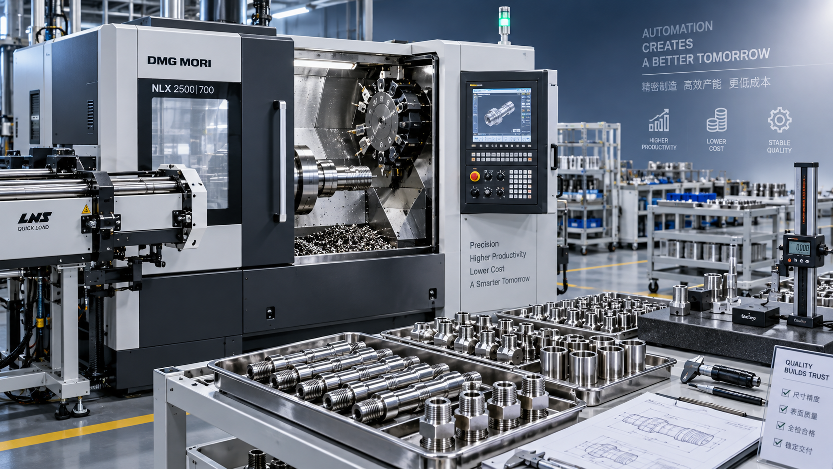
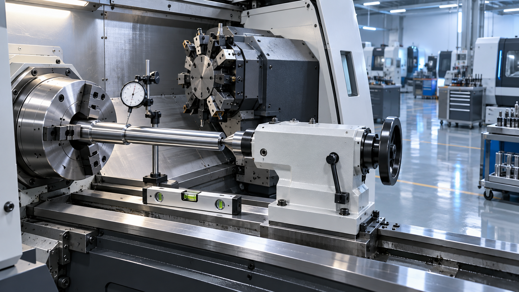
At its core, CNC turning removes material from a rotating workpiece with a stationary or controlled-moving cutting tool. The workpiece is usually clamped in a chuck, collet, or between centers, and the machine controls the tool movement along defined axes to create the required geometry. This makes CNC turning especially efficient for parts where the main features are concentric around a central axis.
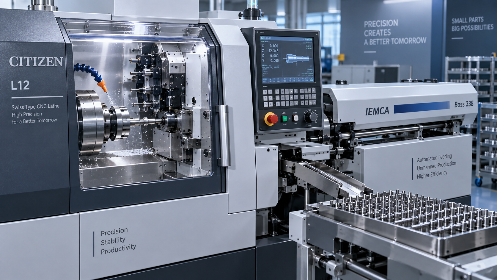
Typical operations include facing, straight turning, taper turning, grooving, parting, threading, boring, drilling on center, and contouring. On more capable machines, live tooling and sub-spindles can add milling, cross-drilling, and part transfer, which reduces handling between operations. Even so, the basic logic remains the same: the part rotates, and the tool removes material in a controlled path.
What matters during planning is not just the machine motion, but the way the feature is generated. An outer diameter turned in a single stable pass is very different from a long slender shaft that deflects under cutting force. A short threaded nose near the chuck behaves differently from a deep internal bore with limited rigidity. In other words, the same CNC turning process can be very stable for one geometry and much less forgiving for another.
Before reviewing tolerances, identify the real control feature
One common mistake is treating all dimensions on a drawing as equally difficult. They are not. In CNC turning, the dimension that controls function is often not the largest diameter or the tightest number on the page. It may be the relationship between surfaces: concentricity between a bore and an outer diameter, runout at a sealing surface, shoulder location relative to thread position, or the consistency of a groove width that mates with another component.
For this reason, a useful review starts with three questions. First, which feature actually determines assembly or performance? Second, which datum strategy will be used in machining and inspection? Third, can those datums remain stable across all operations, or will the part need to be reclamped and re-referenced? The answers usually reveal whether the drawing is a natural fit for CNC turning or whether another approach, or a combined process route, makes more sense.
Key tolerances in CNC turning that deserve close attention
When people ask what tolerances CNC turning can hold, the honest answer is that it depends on the part geometry, material, machine condition, workholding method, cutting strategy, and inspection method. A drawing should therefore be reviewed by tolerance type, not by a single blanket expectation.
Diameter tolerance is often the first concern. CNC turning is well suited to controlling external and internal diameters, especially on rigid parts with short tool overhang and stable cutting conditions. But small diameter tolerance alone does not guarantee function if the feature is not aligned properly to the rest of the part.
Length and shoulder location are equally important. Axial dimensions may shift because of tool wear compensation, insert nose geometry, or variation in how the workpiece seats during loading. A simple-looking shoulder can become a repeatability issue when multiple axial features stack up.
Concentricity and runout often matter more than raw size tolerance. A shaft may meet diameter specification and still fail in use if bearing surfaces do not run true to one another. These characteristics are closely tied to setup strategy. Features produced in one clamping condition are usually easier to keep aligned than features split across multiple setups.
Surface finish also needs realistic review. CNC turning can produce fine finishes, but tool condition, feed rate, material grade, and vibration all influence the result. A finish requirement on an accessible outer diameter is not the same challenge as the same requirement deep inside a small bore.
Thread quality depends on pitch control, insert form, material behavior, and whether the thread is external or internal. Threaded features often look standard on the drawing, but inspection method and mating expectations should be clarified early.
Geometric stability on thin walls or long parts is another frequent issue. Even if the machine can physically create the nominal dimensions, the part may spring, chatter, or deform during cutting. In these cases, the problem is not programming alone. It is the interaction of geometry and cutting force.
How to judge whether a part is a good fit for CNC turning
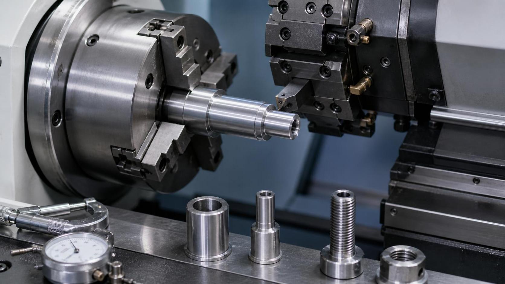
The best-fit part types for CNC turning usually share one trait: their main functional features are rotational and can be produced efficiently around a single axis. Typical examples include shafts, sleeves, bushings, spacers, pins, rollers, threaded connectors, hubs, simple nozzles, bearing seats, rings, and many valve or coupling elements.
These parts tend to work well because the process naturally creates roundness, diameter control, and repeatable axial features when the geometry is accessible. If a part can be completed in one or a small number of stable setups, CNC turning often offers a strong balance of precision and throughput.
Parts become less ideal when the non-rotational features dominate the design. A component with extensive side pockets, off-axis surfaces, multiple angular faces, or heavy interrupted cuts may still start on a lathe, but CNC turning is no longer the whole answer. In that case, a machining center, mill-turn platform, or a staged process may be more appropriate.
A practical screening method is to ask whether the part's critical dimensions are mostly diameters, coaxial bores, faces, grooves, and threads. If yes, CNC turning is likely a good candidate. If the key features are mostly prismatic or off-center, the process fit becomes weaker.
Common misjudgments that cause trouble later
One frequent misunderstanding is assuming that a rotational blank automatically means a turning-first solution. Sometimes that is true, but not always. If the drawing places the highest functional importance on cross-holes, flats, side features, or milled windows, then turning may only be a preliminary operation.
Another mistake is assigning unnecessarily tight tolerances to non-critical surfaces. That can force extra passes, increased inspection, or secondary finishing without improving function. On the other side, some drawings leave critical relationships too loose, especially around runout or datum structure, which creates ambiguity and quality disputes later.
There is also a tendency to evaluate manufacturability by machine capability alone. A modern CNC lathe may be highly capable, but process capability still depends on material, batch size, feature order, and part rigidity. A geometry that is technically possible may still be a poor production choice if consistency becomes difficult to maintain.
A practical review method for CNC turning parts
- Start with function, not just shape. Identify which surfaces locate, seal, rotate, thread, or transmit load. Those are the features that need the most careful tolerance review.
- Group features by turning compatibility. Separate rotational features from off-axis or prismatic features. This quickly shows whether the part is truly turning-dominant or only partially suited to CNC turning.
- Check whether critical features can be completed in one setup. If a feature relationship depends on reclamping, the process risk usually rises.
- Review thin sections, long unsupported lengths, and deep bores. These are common sources of chatter, taper, deflection, and finish instability.
- Evaluate tolerance by feature type. Do not treat diameter, runout, length, finish, and thread requirements as interchangeable. Each one behaves differently in production.
- Clarify inspection intent early. A tolerance is only useful if the feature can be measured consistently with the chosen datum strategy.
- Consider combined process routes where needed. In many production environments, CNC lathes, machining centers, multi-axis systems, and supporting tooling are used together. That is often the more realistic path for complex parts than forcing everything into one operation.
When CNC turning is the right choice, and when it is not
CNC turning is usually the right choice when the part is axisymmetric, the critical features are concentric, material removal is primarily on diameters and faces, and repeatability matters across multiple pieces. It is especially strong for production of precision cylindrical components where stable workholding and straightforward tool access can be maintained.
It becomes less suitable as the part moves away from rotational logic. If the geometry demands frequent indexing, extensive side machining, or complex non-round surfaces, a different platform may provide a cleaner and more controllable route. In some cases, the right answer is not turning versus milling, but a sequence that uses both in a deliberate order.
For teams reviewing suppliers or internal manufacturing routes, this distinction matters because it changes quoting assumptions, fixture planning, cycle balance, and quality control. A part that matches CNC turning well is often easier to standardize. A part that fights the process tends to create recurring engineering questions.
Common Questions
Is CNC turning only for simple round parts?
No. CNC turning can handle more than basic cylinders, including grooves, tapers, threads, bores, contours, and in some cases live-tooled secondary features. The key limit is whether the part's critical geometry remains mostly rotational and accessible in stable setups.
What tolerance matters most in CNC turning?
That depends on function. Many people focus on diameter first, but in practical assemblies, runout, concentricity, shoulder position, and surface finish can be just as important or even more important than nominal size alone.
How do I know if a part is a poor fit for CNC turning?
Warning signs include dominant off-axis features, heavy interrupted surfaces, deep and difficult internal access, thin unsupported walls, and critical relationships that require multiple reclamping steps. Those conditions do not make the part impossible, but they do reduce process efficiency and consistency.
Can one machine complete the entire part?
Sometimes, especially with advanced mill-turn or multi-axis platforms. But many parts are still best produced through a planned combination of CNC turning and additional machining operations. The better question is whether a single-machine route improves control without adding unnecessary complexity.
Closing Thought
The most useful way to evaluate CNC turning is to stop asking whether the part is round enough for a lathe and start asking whether the critical features match the strengths of the process. Once you look at feature relationships, setup stability, tolerance type, and inspection intent together, the decision becomes much clearer. For technical buyers, engineers, and manufacturing planners, that approach usually prevents the most common mismatch: choosing CNC turning because it seems obvious, rather than because it is genuinely the best-fit process for the part.