• Global CNC market projected to reach $128B by 2028 • New EU trade regulations for precision tooling components • Aerospace deman
NYSE: CNC +1.2%LME: STEEL -0.4%

Common CNC Machine for Metalworking Mistakes That Lead to Chatter and Poor Finish

Why Surface Finish Problems Still Appear in Real Production
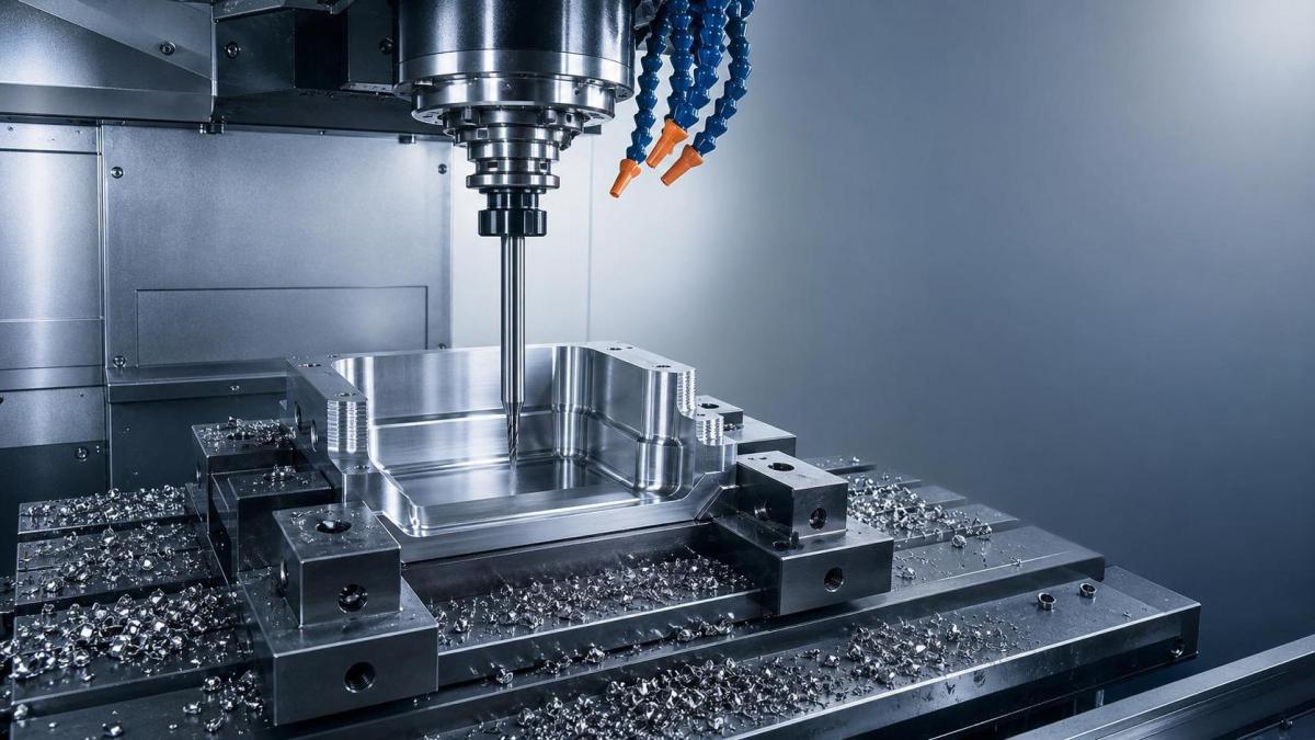
A CNC Machine for Metalworking is built for repeatable accuracy, but chatter and poor finish still appear in daily machining.
The issue is rarely one dramatic failure. More often, several small setup errors combine and create vibration, deflection, and unstable cutting pressure.
That matters across the broader manufacturing chain. Automotive shafts, aerospace brackets, energy parts, and electronics housings all depend on reliable surface quality.
In a smart manufacturing environment, a poor finish does more than affect appearance. It can slow inspection, disrupt assembly, and reduce confidence in process capability.
A common mistake is to blame the machine first. In actual operation, the cause is often linked to tool overhang, clamping rigidity, worn holders, or an unsuitable toolpath.
The better way to evaluate a CNC Machine for Metalworking is by looking at the cutting scene, the part geometry, and the stability margin available in that setup.
Different Parts Create Different Risk Patterns
Not every vibration problem starts from the same place. Thin walls react differently from solid blocks, and long shafts behave differently from compact discs.
On a CNC Machine for Metalworking, the demand changes with material removal rate, unsupported length, corner engagement, and required finish tolerance.
High-volume work usually values repeatable tool life and stable cycle time. Low-volume precision work often puts more pressure on finish, edge quality, and dimensional consistency.
This is why two shops can machine similar materials and still need different process decisions. The part form and fixture condition change the practical limits.
When Long Tools Meet Deep Cavities
Deep pocket milling is one of the most common trouble spots. A long tool reaches the feature, but the extended overhang lowers rigidity immediately.
In this case, a CNC Machine for Metalworking may show chatter marks even when spindle speed and feed look acceptable on paper.
The practical fix is usually not one parameter change. Shorter gauge length, reduced radial engagement, and smoother entry motion often work better together.
When Thin Sections Distort Under Load
Thin ribs, housings, and covers create a different challenge. The cutting system may be rigid enough, but the part itself moves under force.
In these jobs, finish problems on a CNC Machine for Metalworking are often tied to sequence planning, rest material distribution, and where support is removed too early.
A stable result often depends on lighter finishing passes, balanced stock, and fixtures that support the weakest zone instead of only holding the outside contour.
The Shop Floor Mistakes That Most Often Trigger Chatter
Several mistakes repeat across machining centers, CNC lathes, and multi-axis cells. They look minor, but they push the process outside its stable range.
- Using more tool overhang than required for the feature.
- Clamping the part securely, but not rigidly enough near the cutting zone.
- Running worn inserts because edge wear is not yet visible to the eye.
- Copying feeds and speeds from another material grade or holder type.
- Ignoring spindle, holder, or pull stud condition during repeated production runs.
- Using abrupt tool entries that spike cutting load at corners or tight walls.
On a CNC Machine for Metalworking, chatter is often the visible symptom, not the root cause. The root cause is usually a weak link in the setup chain.
That chain includes toolholder balance, spindle health, workholding design, material variation, coolant delivery, and even part loading consistency on automated lines.
In High-Volume Runs, Stability Matters More Than Aggressive Numbers
A common misjudgment in serial production is assuming the fastest cutting data will also be the most economical over time.
For a CNC Machine for Metalworking running batches around the clock, unstable cutting creates hidden losses through insert variation, offset drift, and rework accumulation.
This is especially relevant in automotive and electronics production, where takt time matters but consistent finish also affects downstream fit and sealing performance.
A slightly lower spindle speed with cleaner chip evacuation may outperform a more aggressive setting once tool life and quality consistency are measured together.
In real production cells, the best process window is often the one that absorbs material variation and machine-to-machine differences without visible finish loss.
In Precision Work, Small Setup Details Carry More Weight
Aerospace components, energy equipment parts, and critical bearing surfaces usually have tighter finish expectations and less room for corrective polishing.
Here, a CNC Machine for Metalworking must hold stability through every pass, especially when machining hard alloys, interrupted cuts, or complex multi-axis surfaces.
Small issues become more significant in this environment. Slight runout, an uneven clamping face, or poor thermal control can leave visible marks quickly.
The better judgment in this scene is to verify the entire process stack, not only the NC program. Holder quality, probe accuracy, and stock consistency all matter.
Different Scenarios Call for Different Checks
The table below shows why one chatter fix does not fit every case on a CNC Machine for Metalworking.
This kind of comparison helps separate machine limits from setup choices, which is essential in digitally managed production environments.
The Misread Signals That Delay the Real Fix
One frequent error is treating every poor finish as a feed-and-speed issue. Sometimes the parameter change only hides vibration for a short period.
Another misread is assuming a rigid vise or chuck guarantees system stiffness. If the part extends too far, the holding force does not solve the leverage problem.
There is also a tendency to copy a proven process from one CNC Machine for Metalworking to another without checking spindle condition and holder compatibility.
In global production networks, this matters even more. Similar machines across different plants may run different tooling packages, coolant pressure, and maintenance quality.
The result is a process that looks standardized in documentation, but behaves differently on the floor.
How to Build a More Stable CNC Machine for Metalworking Process
A stable process starts with a disciplined check of the cutting scene before chasing advanced optimization.
- Measure actual tool overhang and compare it with the minimum needed for clearance.
- Check holder runout at the cutting diameter, not only near the taper.
- Review fixture support relative to the real cutting direction and peak load point.
- Separate roughing and finishing strategies instead of using one compromise program.
- Track finish defects by feature location to identify whether the trigger is toolpath, support, or wear.
- Confirm that the chosen CNC Machine for Metalworking settings remain stable across multiple parts, not just the first trial piece.
Where automation and flexible production lines are expanding, these checks become part of process control, not just operator habit.
That is how a CNC Machine for Metalworking supports both precision manufacturing and efficient throughput without trading one for the other.
What to Clarify Before the Next Setup Change
Before changing parameters again, define the actual scenario. Is the instability coming from the tool, the part, the fixture, or the transfer of a process between machines?
Then compare the operating conditions that matter most: feature depth, wall strength, support method, tool reach, material behavior, and finish target.
For any CNC Machine for Metalworking, the most useful next step is to build a simple internal checklist around these variables and review it before release.
That approach reduces repeated trial cuts, improves finish consistency, and makes future process decisions more reliable across changing production demands.
Recommended for You
 Is Learning CNC Programming Worth It for Shop Owners Seeking Higher Margins?CNC Machining Technology Center
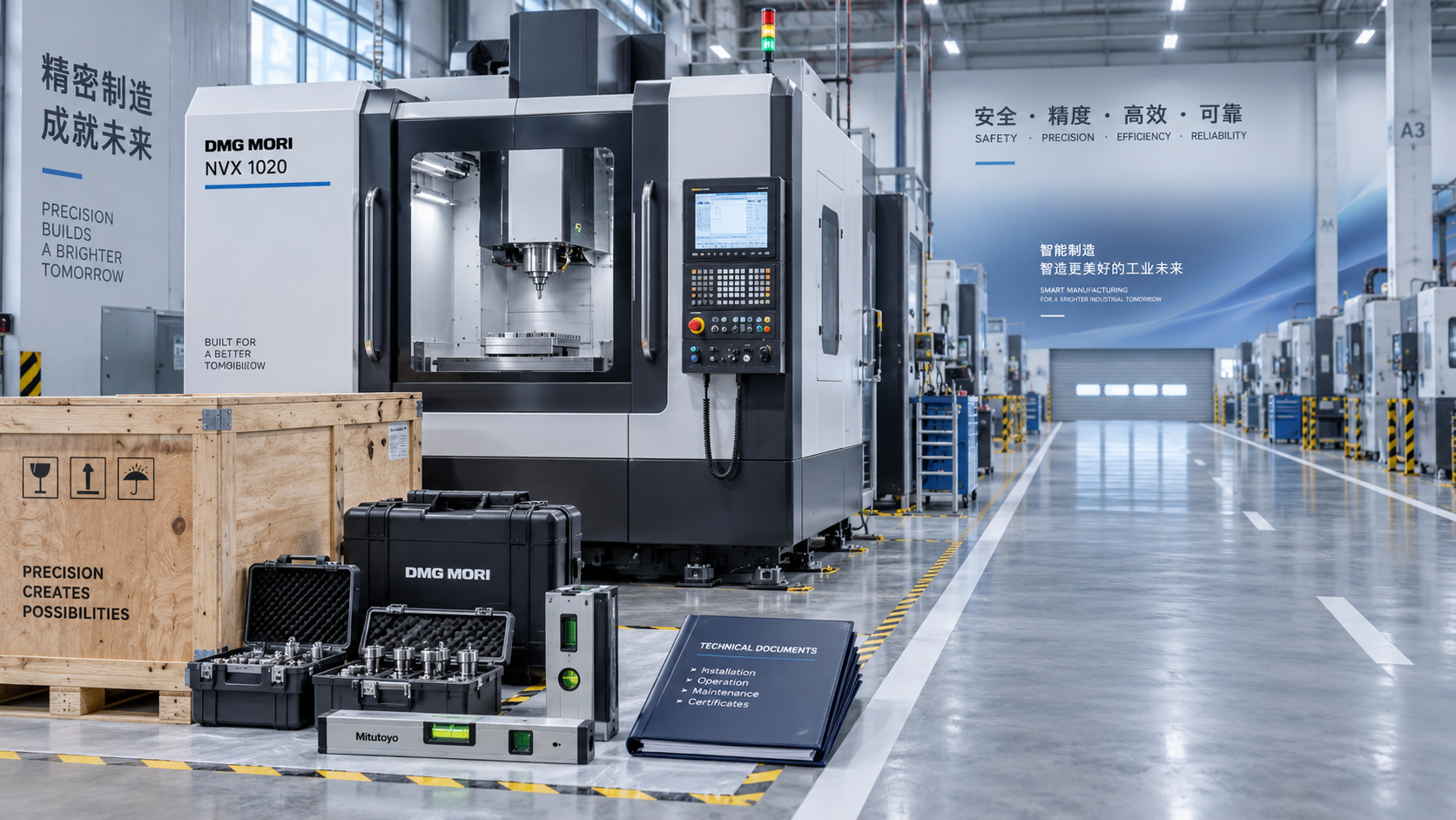
 CNC Machine Arrival Inspection: Check Shipping Damage, Accuracy, Safety, and DocumentsCNC Machining Technology Center
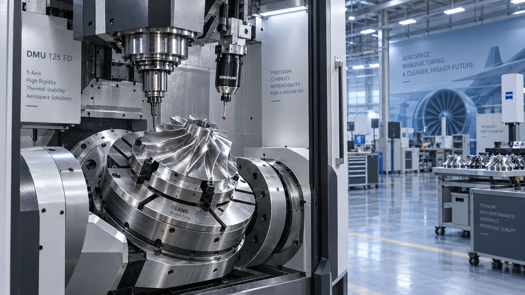
 How to Select a Machine Tool for Aerospace Parts with Tight Tolerances?Machine Tool Industry Editorial Team
 How to Select CNC Equipment for High-Mix, Low-Volume ProductionCNC Machining Technology Center
 Can CNC Machining Inconel Control Tool Wear in High-Temperature Aerospace Parts?CNC Machining Technology Center
 Machine Tool Market Outlook: Demand Drivers, Capacity Shifts, and Investment RisksManufacturing Market Research Center

Aris Katos
Future of Carbide Coatings
15+ years in precision manufacturing systems. Specialized in high-speed milling and aerospace grade alloy processing.
▶
Is Learning CNC Programming Worth It for Shop Owners Seeking Higher Margins?CNC Machining Technology Center▶
How to Select CNC Equipment for High-Mix, Low-Volume ProductionCNC Machining Technology Center▶
Can CNC Machining Inconel Control Tool Wear in High-Temperature Aerospace Parts?CNC Machining Technology Center▶
How Automated Precision Machining Maintains Tolerance in High-Mix ProductionCNC Machining Technology Center▶
CNC Programming Explained: From CAD Models to Reliable Shop-Floor ToolpathsCNC Machining Technology Center
Mastering 5-Axis Workholding Strategies
Join our technical panel on Nov 15th to learn about reducing vibrations in thin-wall components.

Providing you with integrated sanding solutions
Before-sales and after-sales services
Comprehensive technical support