• Global CNC market projected to reach $128B by 2028 • New EU trade regulations for precision tooling components • Aerospace deman
NYSE: CNC +1.2%LME: STEEL -0.4%

Can CNC Machining Inconel Control Tool Wear in High-Temperature Aerospace Parts?
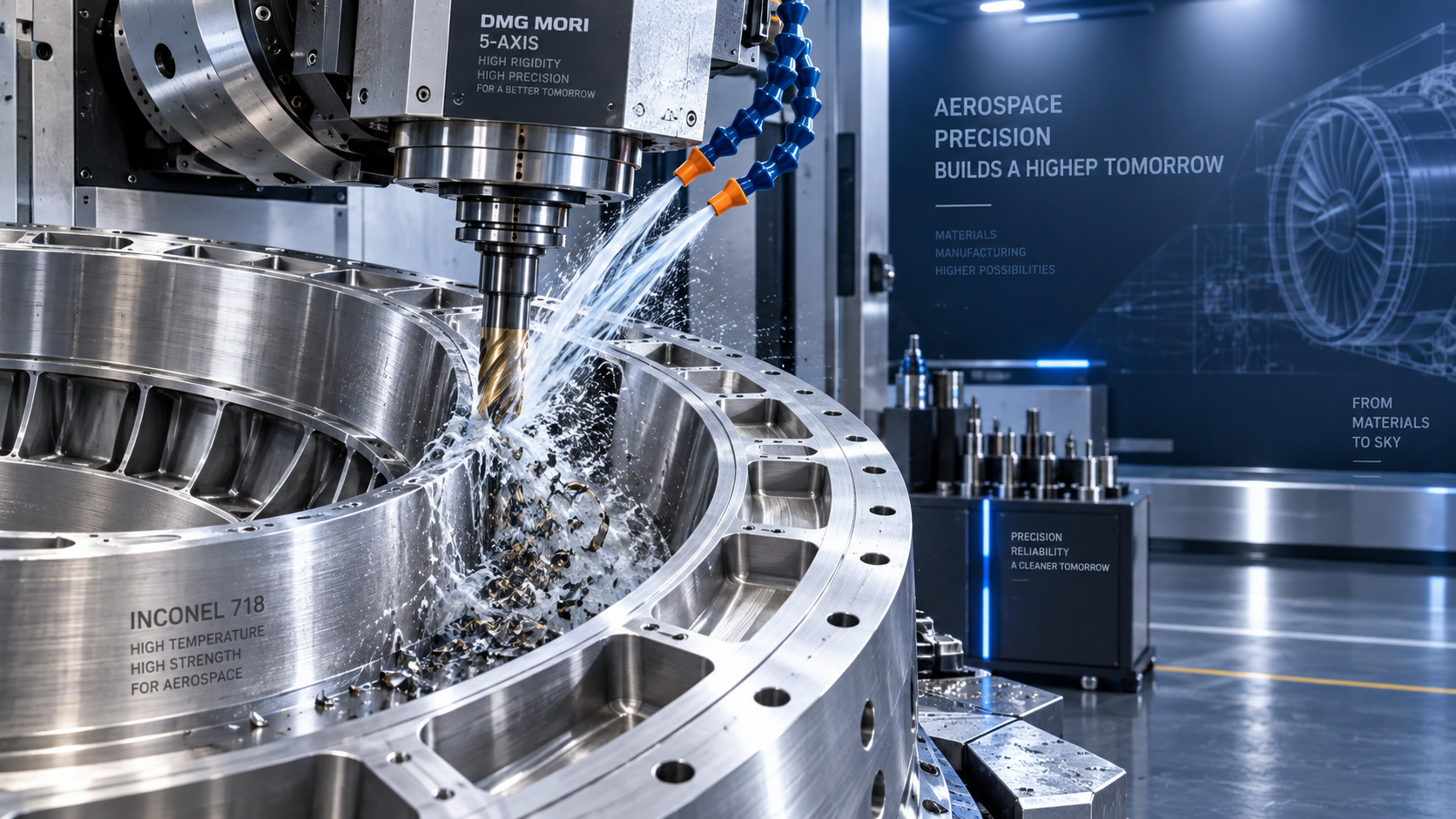
Yes—CNC machining can control tool wear in Inconel aerospace parts, but it cannot eliminate wear as a process variable. The realistic objective is stable, predictable tool life while preserving dimensional accuracy, surface integrity, and repeatability across a qualified production batch. Inconel’s low thermal conductivity, strong work-hardening response, high-temperature strength, and tendency to form built-up edge make it one of the more demanding aerospace materials to machine. A process that merely produces an acceptable first part is not necessarily capable of maintaining control through repeated cycles.
The key question is therefore not whether a machine can cut Inconel, but whether the complete machining system can remove heat and chips consistently, prevent rubbing and work hardening, maintain tool engagement within a stable range, and detect wear before it affects the component. For high-temperature aerospace parts, tool wear control is inseparable from process control.
Why Inconel accelerates tool wear
Nickel-based superalloys such as Inconel 718 and Inconel 625 retain strength at temperatures where many conventional alloys soften. That property is essential in turbine, combustion, exhaust, and high-temperature structural applications, but it also means the cutting zone remains mechanically demanding. Rather than softening readily under the tool, the material continues to resist deformation.
Inconel also conducts heat poorly compared with many steels and aluminum alloys. A significant share of cutting heat stays concentrated near the cutting edge, workpiece surface, and chip-tool interface. If heat is not controlled, the cutting edge can undergo rapid crater wear, flank wear, coating degradation, edge chipping, or plastic deformation.
Work hardening adds another layer of difficulty. When a cutting edge rubs rather than shears, or when a finishing pass is too shallow to cut below the hardened layer created by the prior pass, the next tool engagement begins in more resistant material. This can create a damaging cycle: increased force causes more heat, more heat worsens wear, and wear further increases rubbing.
These mechanisms explain why the phrase can metal machining handle Inconel without tool wear issues needs qualification. The answer is no if “without tool wear” means no meaningful degradation. The answer is yes if it means using a controlled process that makes wear gradual, measurable, and compatible with the required quality and production economics.
Tool wear is often a symptom, not the original failure
Premature tool failure is frequently blamed on the tool grade alone. Tool material matters, but it is only one part of the system. In aerospace machining, unstable wear often points to a mismatch between material condition, machine capability, programming strategy, workholding, coolant access, and tool geometry.
A worn insert can reveal several different underlying problems:
- Uniform flank wear may indicate that the process is fundamentally stable but the selected grade, cutting speed, or tool-change interval does not match the duty cycle.
- Notching at the depth-of-cut line can indicate work-hardened material, scale or surface contamination, repeated engagement at the same location, or insufficiently varied toolpath strategy.
- Chipping at the cutting edge often suggests vibration, intermittent engagement, weak workholding, excessive radial engagement, inadequate edge preparation, or a brittle tool grade for the operation.
- Crater wear is commonly associated with excessive temperature at the chip-tool interface and may require a review of speed, coolant delivery, chip control, or cutting-tool substrate and coating.
- Built-up edge and poor surface finish can result from adhesion, unstable chip evacuation, low effective cutting action, or a parameter window that promotes rubbing.
Replacing the tool without identifying the wear pattern can temporarily restore output while leaving the process unstable. For an aerospace component with tight feature relationships, that instability may later appear as variation in bore size, profile error, burr formation, residual stress, or surface damage rather than an obvious broken cutter.
Machine rigidity and dynamics determine whether the strategy is usable
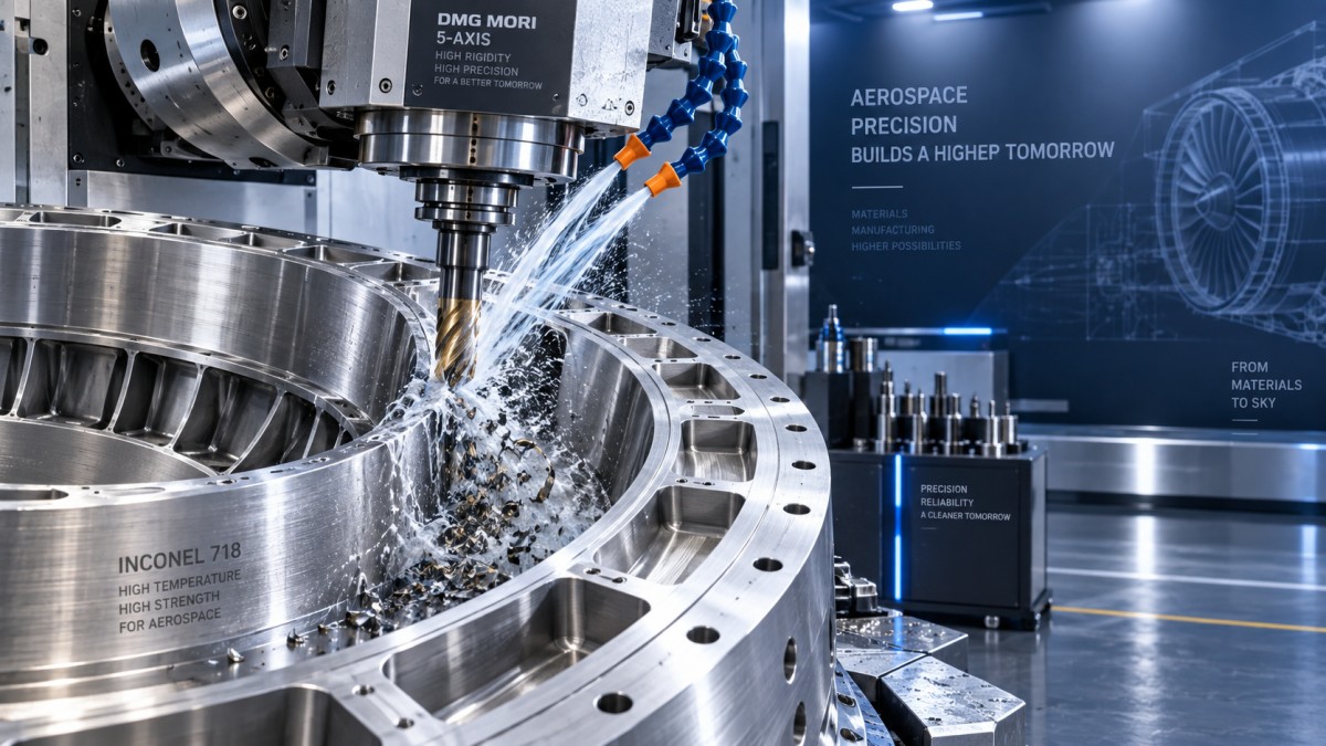
A CNC program designed for Inconel cannot compensate for a machine that lacks sufficient rigidity, spindle torque, thermal stability, or damping. High-temperature aerospace parts often include deep cavities, thin walls, interrupted features, complex fillets, and difficult-to-reach surfaces. These geometries make dynamic stability as important as nominal spindle power.
Machine-tool evaluation should focus on behavior under load, not only published specifications. Useful questions include whether the spindle can sustain torque in the intended speed range, whether the toolholder interface is appropriate for the cutter diameter and overhang, how well the axis system controls motion during high-engagement paths, and whether vibration becomes visible in surface finish or tool wear.
Excessive tool overhang is especially costly in Inconel. A long reach can be unavoidable in deep aerospace cavities, but each additional increment of unsupported length reduces stiffness. The result is often micro-chipping that may not be visible immediately yet degrades surface quality and causes unpredictable dimensional drift. Shortest-possible gauge length, appropriate holder selection, and toolpath planning that avoids unnecessary reach are practical wear-control measures, not minor setup details.
Workholding deserves the same scrutiny. If a part deflects during roughing and relaxes during finishing, the machine may produce acceptable dimensions at one stage but leave variable stock for the next. That stock variation changes cutter engagement, and changing engagement changes wear. Fixtures must support the component without distorting it, particularly for thin-walled rings, casings, brackets, and contoured structural parts.
Tool selection must match the operation, not simply the alloy
There is no single “best” cutter for Inconel. Roughing, semi-finishing, finishing, slotting, drilling, boring, and thread generation impose different thermal and mechanical loads. A carbide grade that performs well in a stable side-milling operation may fail quickly in an interrupted cut or deep internal feature.
For milling, cemented-carbide tools with coatings designed for high-temperature alloy machining are commonly used, but the best choice depends on edge preparation, flute form, helix geometry, rigidity, and coolant access. A sharp edge can lower cutting forces, yet a stronger honed edge may survive better where interruptions or vibration are present. The trade-off is not academic: an overly sharp edge can chip, while an overly blunt edge can generate heat through rubbing.
Indexable tooling can be effective for heavier stock removal where insert economy and predictable indexing are important. Solid-carbide end mills are often favored for smaller radii, complex contours, and finishing features that require continuous geometry. Ceramic tools may be applicable in certain high-speed turning conditions, but their brittleness, coolant sensitivity, and interruption limits make them unsuitable as a universal answer. Their use requires a machine and operation specifically suited to ceramic cutting behavior.
Toolholder choice is equally relevant. Hydraulic, shrink-fit, and precision collet systems can provide better concentricity than poorly maintained general-purpose holders. Runout causes one tooth to carry more load than the others, producing uneven wear and shortened life. In a material already prone to high cutting temperature, that imbalance can quickly become a quality issue.
Coolant delivery is part of the cutting geometry
Flood coolant alone may be insufficient where the cutting zone is shielded by chips, cavity walls, or a long tool body. The purpose of coolant in Inconel machining is not simply to reduce general machine temperature. It must reach the interface where heat and adhesion are concentrated, assist chip evacuation, and prevent chips from being recut.
High-pressure, directed coolant can improve access in many turning, drilling, and milling operations, particularly where chip packing is a risk. Through-tool coolant is valuable for deep-hole drilling and internal machining because external flow may not reach the active edge consistently. The relevant evaluation is not pressure as an isolated number; it is whether the nozzle or internal channels maintain delivery at the cutting edge throughout the actual toolpath.
Coolant strategy must also be consistent. Sudden or poorly controlled thermal cycling can contribute to edge cracking in some conditions. Where a process is intended to run wet, intermittent flow caused by poor nozzle positioning, clogged filters, or insufficient supply should be treated as a process fault. The same applies to coolant concentration and cleanliness. Contaminated fluid does not create the primary wear mechanism, but it can reduce lubrication performance and impair chip removal.
Parameter control means managing engagement, not choosing a single speed and feed
Published cutting data is a starting point, not a qualified machining process. Inconel reacts strongly to changes in radial engagement, axial depth, toolpath curvature, entry condition, and cutter immersion. A parameter that is stable in a straight open wall may become destructive in a tight corner where engagement rises sharply.
Modern high-efficiency milling strategies can help because they aim to maintain a more consistent chip load while using controlled radial engagement and greater axial use of the cutter. Their value is not that they automatically permit aggressive machining. Their value is that they reduce sudden load peaks, distribute wear over more of the cutting edge, and make the thermal condition more repeatable when machine rigidity and programming are adequate.
Conventional full-width slotting in Inconel is particularly demanding because chip evacuation, heat removal, and radial force all become less favorable. If slotting cannot be avoided, the process requires close attention to tool geometry, coolant access, chip clearing, and feed control. Trochoidal or adaptive paths may reduce continuous full engagement, but they do not solve poor workholding or inadequate machine dynamics.
Finishing needs separate qualification from roughing. A common mistake is to assume that a light finishing pass is always safer. If the pass is too light relative to edge radius or the hardened surface layer, the tool may rub rather than cut. Finishing stock must be sufficient for clean shearing, while the tool must remain sharp and stable enough to protect surface finish. Where fatigue performance is critical, surface integrity requirements may be more important than minimizing cycle time.
Material condition and starting stock can alter the process window
Inconel is not a uniform machining condition simply because the alloy designation is the same. Product form, heat treatment condition, prior forging, residual stress, grain structure, and surface condition all influence cutting response. Forged or heat-treated aerospace stock may present harder zones, scale, or variable material response near surfaces. A process proven on bar stock should not automatically be assumed valid for a near-net forging or an additively manufactured blank.
Technical evaluation should confirm the actual material specification and condition before setting a tool-life expectation. This includes traceability of the supplied material, defined heat-treatment state, and the amount and location of machining allowance. A component with inconsistent remaining stock may require different roughing and finishing logic from one machined from a uniform billet.
For aerospace work, material removal can also release residual stress. A part may shift after roughing, unclamping, or heat treatment, even if the cutter remained stable. Separating roughing from finishing, allowing for stress-relief steps where the manufacturing route requires them, and establishing meaningful in-process datum control can prevent tool wear from being blamed for geometric movement caused by the workpiece itself.
Wear control must be linked to inspection and replacement criteria
Tool life should not be managed only by operator judgment or by waiting for visible damage. A reliable process defines what constitutes acceptable wear for each critical operation and links that condition to measurable outputs. Depending on the feature, those outputs may include dimensional trend, spindle load behavior, surface roughness, burr condition, tool offset adjustment, or direct inspection of inserts and cutting edges.
Fixed tool-change intervals can be appropriate when the incoming stock, machine condition, and cutting cycle are highly controlled. Where part geometry or stock allowance varies, condition-based monitoring may be more useful. Spindle power signatures, acoustic monitoring, or in-machine probing can provide additional information, but they should not be treated as substitutes for understanding the actual wear mechanism. Monitoring is most valuable when process limits have been established through qualification.
Tool offsets also require discipline. Repeatedly compensating for a drifting tool can conceal progressive wear until the surface finish, profile, or feature position is outside tolerance. An offset trend should prompt examination of tool condition and process stability rather than endless correction. For critical aerospace features, the decision threshold should reflect the required surface integrity and geometric capability, not merely whether a part can still be brought into size.
What a credible Inconel machining qualification should demonstrate
A convincing capability assessment is not a single successful cut. It should show repeatability over multiple tools or production-equivalent cycles, using the intended material condition, workholding arrangement, coolant method, and inspection route. The evaluation should include the most demanding geometries: deep cavities, thin sections, interrupted regions, close-tolerance bores, or difficult corner transitions where applicable.
The most useful evidence is a coherent relationship between tool wear, machine load, dimensional results, and surface condition. If tool life is presented without showing what happens to size and finish near the end of that life, the result is incomplete. Likewise, a good surface finish on an early part does not establish that the process protects the surface after repeated thermal loading.
Inconel machining becomes manageable when tool wear is treated as an engineered and monitored variable rather than an unavoidable surprise. The strongest process combines rigid equipment, stable workholding, operation-specific tooling, directed coolant, controlled chip load, adequate finishing allowance, and wear-based intervention criteria. Under those conditions, CNC machining can produce high-temperature aerospace components with reliable accuracy. Without that systems approach, even premium cutting tools are likely to deliver inconsistent life and uneven part quality.
NEXT ARTICLE
Recommended for You
 Can CNC Machining Inconel Control Tool Wear in High-Temperature Aerospace Parts?CNC Machining Technology Center
 Machine Tool Market Outlook: Demand Drivers, Capacity Shifts, and Investment RisksManufacturing Market Research Center
 Zero-Point Clamping or Modular Fixtures? Choosing a Faster CNC Changeover SystemCNC Machining Technology Center
 How to Cut CNC Fixture Changeover Time Without Sacrificing Part AccuracyCNC Machining Technology Center
 When Does CNC Turning Pay Off? A Break-Even Guide by Annual Part VolumeMachine Tool Industry Editorial Team
 Machine Tool Standards by Country: What Importers Must Verify Before PurchaseManufacturing Policy Research Center


Aris Katos
Future of Carbide Coatings
15+ years in precision manufacturing systems. Specialized in high-speed milling and aerospace grade alloy processing.
▶
Can CNC Machining Inconel Control Tool Wear in High-Temperature Aerospace Parts?CNC Machining Technology Center▶
How Automated Precision Machining Maintains Tolerance in High-Mix ProductionCNC Machining Technology Center▶
CNC Programming Explained: From CAD Models to Reliable Shop-Floor ToolpathsCNC Machining Technology Center▶
How Multi-Axis Machining Produces Complex Components With Fewer SetupsCNC Machining Technology Center▶
How Much Does CNC Programming Software Cost in 2026?CNC Machining Technology Center
Mastering 5-Axis Workholding Strategies
Join our technical panel on Nov 15th to learn about reducing vibrations in thin-wall components.

Providing you with integrated sanding solutions
Before-sales and after-sales services
Comprehensive technical support