• Global CNC market projected to reach $128B by 2028 • New EU trade regulations for precision tooling components • Aerospace deman
NYSE: CNC +1.2%LME: STEEL -0.4%

How to Select CNC Equipment for High-Mix, Low-Volume Production
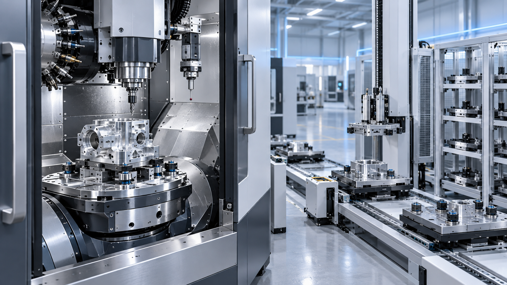
For high-mix, low-volume work, the right CNC machine is the one that keeps the next job from becoming a disruption. A machine with impressive peak cutting figures can still be a poor fit when every shift brings different materials, workholding methods, tolerances, and program structures. The selection should begin with the part family and the frequency of changeover, then test whether the machine, control, tooling, and material-handling approach support that reality.
Start by separating the workload into recurring part families rather than treating every drawing as unique. Group parts by geometry, stock form, material, critical features, and process route. A family of prismatic aluminum housings has very different equipment needs from a mix of stainless valve bodies, hardened steel inserts, and thin-walled aerospace brackets. The goal is not to find a universal machine for every possible job. It is to identify the broadest useful operating window without accepting avoidable compromises in setup time, rigidity, inspection access, or programming effort.
Build the Selection Around Part Changeover
High-mix production loses time in activities surrounding cutting: locating fixtures, loading tools, proving programs, measuring first-off parts, changing jaws, and recovering a stable process after a new job begins. Machine capacity should therefore be judged by productive time across a sequence of different jobs, not by the cycle time of one idealized component.
Examine how often a part needs a different vise, chuck, collet, fixture plate, pallet, tombstone, or rotary setup. If changeovers regularly involve rebuilding workholding from scratch, a larger or faster machine will not solve the main constraint. A machine with a well-designed table, accessible clamping zones, repeatable locating features, and adequate clearance around the workpiece often delivers more usable flexibility than a machine selected solely for travel.
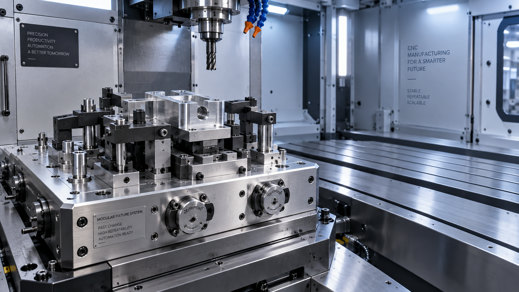
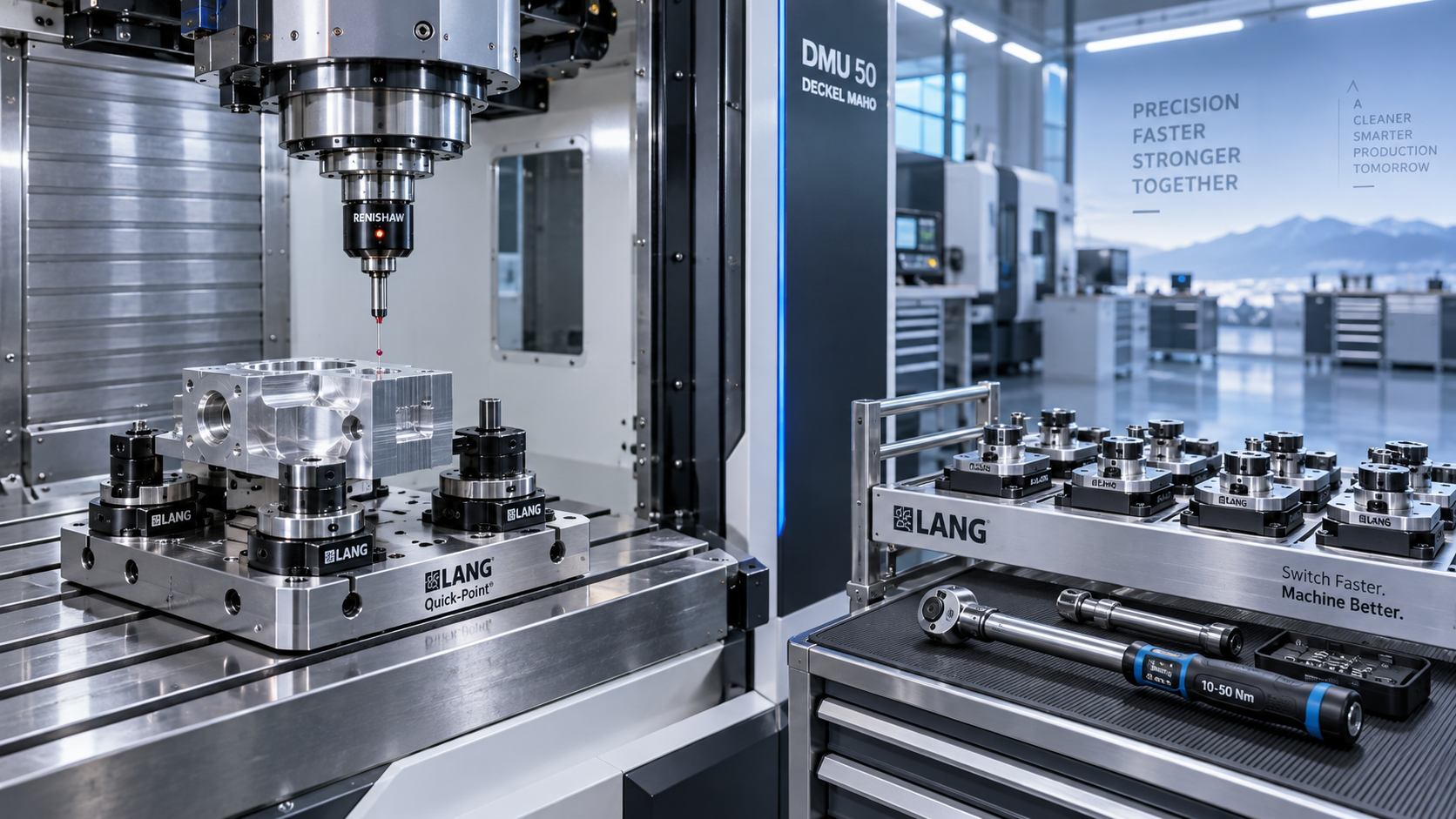
Fixture standardization has a direct effect on equipment choice. Zero-point pallets, repeatable subplates, modular jaws, and common datum conventions can reduce setup variation, but they consume table height and working envelope. Confirm the remaining Z-axis clearance with the actual fixture stack, the longest toolholder, and the tallest component. Catalog travel alone is not a reliable indication of usable machining space.
For turning work, consider the full changeover path: chuck jaw replacement, collet system changes, bar feeder interface, part catcher clearance, tool block adjustment, and access for gauging. A turning center that handles a large diameter may still be inefficient for a varied schedule if its chuck configuration takes too long to convert between delicate small parts and heavier forgings.
Choose the Machine Architecture From the Process Route
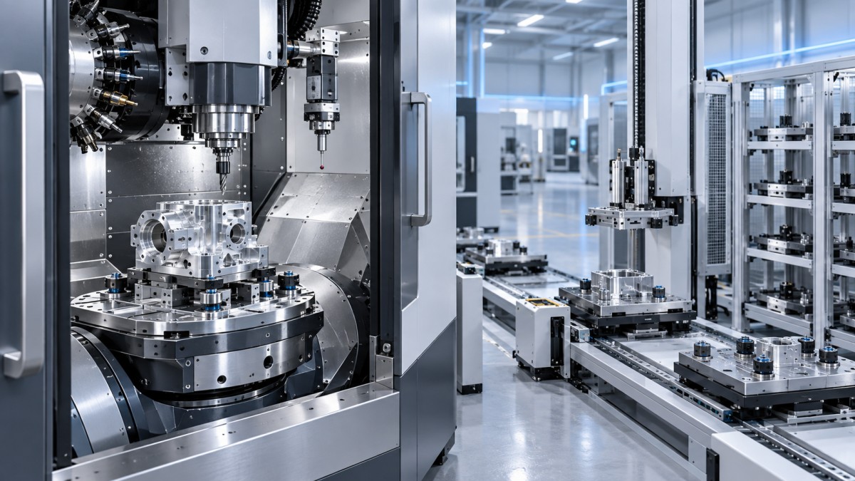
Machine type should follow the number of setups required to complete a part, not just the number of axes shown on a brochure. A three-axis vertical machining center remains highly flexible for plates, brackets, covers, and many prismatic parts when features are accessible from a limited number of orientations. Its relative simplicity can also shorten program proving and make fixturing easier to understand.
A fourth-axis indexer becomes valuable when repeated side features, radial patterns, or multi-face machining would otherwise require several manual re-clamps. The benefit is strongest when indexing reduces datum transfers and fixture handling. Continuous four-axis capability is justified when contouring, helical features, or controlled tool orientation is genuinely part of the work; it should not be assumed necessary simply because parts have curved surfaces.
Five-axis equipment earns its place when it materially reduces setups, reaches compound-angle features, improves access to deep cavities, or allows a shorter cutting tool through part orientation. Shorter tools can improve stiffness and surface control, especially in titanium, stainless steel, and hardened materials. Yet five-axis machining adds complexity in collision control, post-processing, workholding, kinematic verification, and program validation. For a mixed workload dominated by straightforward prismatic parts, a capable three- or four-axis machine with fast setups may produce a more predictable result.
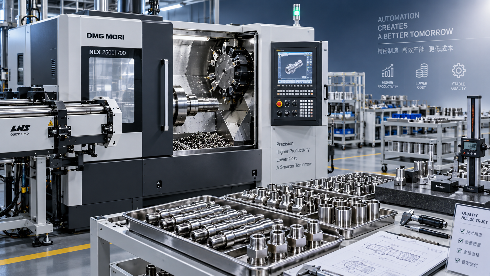
For rotational parts, compare a conventional CNC lathe, a turning center with live tooling, and a mill-turn platform against the actual feature mix. Live tooling and a sub-spindle can remove secondary operations for shafts, flanges, and parts with cross holes or milled flats. That advantage declines when the work routinely includes large prismatic features, extensive off-center machining, or parts that require substantial milling forces. In those cases, moving the part between specialized machines may be more stable than forcing every operation into one complex cycle.
Read Specifications as Interacting Limits
Spindle speed, spindle power, torque, rapid traverse rate, tool capacity, and axis travel are all relevant, but none should be interpreted separately. A high-speed spindle can shorten aluminum machining cycles and support small-diameter tools, yet it may offer insufficient low-speed torque for heavy drilling, large face mills, or aggressive roughing in alloy steel. Conversely, a torque-oriented spindle may be slow to accelerate through the frequent toolpath changes common in small, detailed components.
Review torque across the operating range used by the intended tools. Consider a part requiring a large indexable drill, a modest face mill, and several small end mills. The machine needs to handle all three without creating an artificial bottleneck in one operation. Tool taper, spindle interface, and toolholder availability affect this outcome as much as the nominal motor rating. A robust interface can improve milling stability, but it also influences toolholder mass, cost, and suitability for fine tools.
Axis acceleration and look-ahead performance matter when programs contain dense 2D profiles, engraving, small pockets, mold-like surfaces, or many short moves. Rapid-traverse figures describe non-cutting travel under favorable conditions; they do not predict contour accuracy or actual chip-making time. Request representative cutting demonstrations using geometry and tolerances similar to the intended workload, with the proposed control, postprocessor, and toolpath style.
Tool magazine capacity should cover a typical job plus the tools needed for measuring, finishing, spot drilling, backup cutters, and common deburring operations. Oversizing the magazine is not automatically beneficial, but too little capacity causes preventable intervention. High-mix schedules benefit from organized tool data, reliable offset management, and the ability to retain commonly used tools while preparing job-specific cutters.
Accuracy Must Be Evaluated Over a Working Shift
Positioning claims do not by themselves describe the condition of a finished part. High-mix work repeatedly exposes machine behavior after warm-up, after a tool change, at different table positions, and under varied cutting loads. The relevant question is whether the machine holds the required dimensions, feature relationships, and surface condition through the actual process sequence.
Thermal behavior deserves careful attention where tolerances are close or the job mix moves between heavy roughing and delicate finishing. Spindle growth, ball-screw heat, coolant temperature variation, and ambient changes can move a process even when static inspection appears satisfactory. Thermal compensation can be useful, but it should be assessed with representative cycles rather than accepted as a substitute for stable machine construction and controlled setup practice.
Rigidity is equally contextual. A compact machine can perform accurately on small aluminum components but deflect under long-reach milling of steel or cast iron. Evaluate the longest expected tool projection, not only the shortest tool shown during a demonstration. Thin-wall work introduces a different problem: excessive cutting force, poor support, and unstable tool engagement may distort the component even when the machine itself is rigid. Equipment selection must be paired with a viable clamping strategy and cutting approach.
Ask how probing is integrated into the machine environment. A spindle probe can reduce setup uncertainty by establishing work offsets from actual part datums, checking fixture position, and verifying critical features before unloading. Tool measurement systems reduce errors caused by manual offset entry and allow replacement tools to be qualified consistently. Their value rises sharply when jobs change frequently, but the process still needs clear rules for probe calibration, stylus condition, tool-break response, and exception handling.
Programming and Control Integration Affect Usable Flexibility
A flexible machine is limited by how quickly reliable programs reach the spindle. Verify that the CNC control supports the intended CAD/CAM workflow, postprocessor, probing cycles, coordinate transformations, tool-center-point control where relevant, and program storage requirements. A control that is familiar in isolation may still create friction when its postprocessor handling, file transfer method, or macro behavior does not match the established process.
For multi-axis work, simulation should include the complete machine model, fixtures, toolholders, stock condition, and rotary-axis motion. Collision avoidance based only on the finished model is insufficient because many problems occur during approach, retract, indexing, and tool change. Confirm that the selected machine’s kinematic model is available to the programming system and that postprocessor support is maintained as control software changes.
Program reuse also deserves a practical review. Similar parts often share machining strategies but differ in datum positions, stock allowance, hole patterns, or finish requirements. Parametric programming, standard setup sheets, reusable fixture coordinates, and consistent tool libraries reduce rework when these variations are controlled. They become risky when informal edits accumulate without revision discipline. The machine choice should support traceable program handling rather than encourage isolated files and undocumented offset changes.
Automation Should Protect Flow, Not Add Fragility
Automation is useful in high-mix environments when it removes repeatable handling without making changeovers harder. Pallet changers are effective for parts that can be prepared offline on common fixture plates. They are less compelling when each job requires a unique, time-consuming fixture build that cannot be completed away from the machine. A pallet system also needs enough staging space, clear pallet identification, and a method to prevent the wrong program from running against the wrong setup.
Robotic loading can fit small batches of stable blanks, especially where a common gripper range and reliable orientation method exist. The limitation is often not robot reach but variation in stock, burrs, part presentation, and gripping surfaces. A robot cell should be assessed as a complete process: raw material presentation, machine door cycle, chuck or vise confirmation, part presence sensing, finished-part handling, and recovery after an interrupted cycle.
Unattended capability is not the same as unattended production. Tool life variation, chip accumulation, coolant condition, fixture contamination, and inspection requirements determine how long a process can run without attention. Where batch sizes are small, modest automation that enables offline setup or lights-out completion of a stable repeat order may be more valuable than a large system with extensive changeover demands.
Validate the Purchase With Representative Work
The final evaluation should use a short set of parts that exposes the expected range: a component requiring a quick fixture change, a material that challenges torque or tool life, a tolerance-sensitive finishing operation, and a part with awkward access or complex geometry. Include the real workholding concept, planned cutters, target cycle strategy, and measurement approach. A demonstration using ideal tooling, simplified stock, or loosely defined tolerances cannot answer the selection question.
Record what happens before the first chip is cut: fixture installation time, tool loading, probing, program transfer, dry-run effort, and adjustment steps. Then observe chip evacuation, access for inspection, tool-change clearance, recovery from an interrupted cycle, and the effort needed to start a different job. These details reveal whether the machine will remain flexible after installation rather than only appearing capable during a controlled demonstration.
Service access should be reviewed at the same level of detail. Check local technical support arrangements, availability of critical wear parts, controller backup procedures, electrical requirements, foundation and floor-loading needs, chip and coolant connections, and space for maintenance doors or covers. A machine that fits the floor plan but cannot be serviced without moving adjacent equipment creates an avoidable operational constraint.
The strongest choice is usually the machine that completes the intended families with the fewest fragile setups, maintains accuracy through realistic thermal and cutting conditions, and allows the next job to begin with controlled effort. That standard keeps the evaluation focused on productive flexibility rather than isolated catalog specifications.
NEXT ARTICLE
Recommended for You
 How to Select CNC Equipment for High-Mix, Low-Volume ProductionCNC Machining Technology Center
 Can CNC Machining Inconel Control Tool Wear in High-Temperature Aerospace Parts?CNC Machining Technology Center
 Machine Tool Market Outlook: Demand Drivers, Capacity Shifts, and Investment RisksManufacturing Market Research Center
 Zero-Point Clamping or Modular Fixtures? Choosing a Faster CNC Changeover SystemCNC Machining Technology Center
 How to Cut CNC Fixture Changeover Time Without Sacrificing Part AccuracyCNC Machining Technology Center
 When Does CNC Turning Pay Off? A Break-Even Guide by Annual Part VolumeMachine Tool Industry Editorial Team

Aris Katos
Future of Carbide Coatings
15+ years in precision manufacturing systems. Specialized in high-speed milling and aerospace grade alloy processing.
▶
How to Select CNC Equipment for High-Mix, Low-Volume ProductionCNC Machining Technology Center▶
Can CNC Machining Inconel Control Tool Wear in High-Temperature Aerospace Parts?CNC Machining Technology Center▶
How Automated Precision Machining Maintains Tolerance in High-Mix ProductionCNC Machining Technology Center▶
CNC Programming Explained: From CAD Models to Reliable Shop-Floor ToolpathsCNC Machining Technology Center▶
How Multi-Axis Machining Produces Complex Components With Fewer SetupsCNC Machining Technology Center
Mastering 5-Axis Workholding Strategies
Join our technical panel on Nov 15th to learn about reducing vibrations in thin-wall components.

Providing you with integrated sanding solutions
Before-sales and after-sales services
Comprehensive technical support