• Global CNC market projected to reach $128B by 2028 • New EU trade regulations for precision tooling components • Aerospace deman
NYSE: CNC +1.2%LME: STEEL -0.4%

What to Evaluate in a Multi-Axis Machining Center for Tight-Tolerance Complex Parts
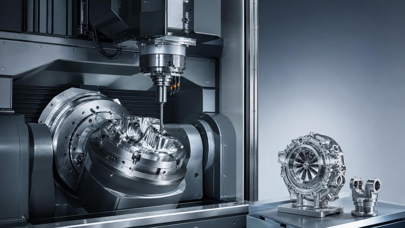
Selecting a Multi-axis Machining Center for Complex Parts is rarely a matter of choosing the machine with the highest axis count or the fastest spindle on paper. For tight-tolerance work, the central question is more practical: can the machine hold geometry, surface quality, and repeatability across long cycles, changing temperatures, difficult materials, and real production variation?
That distinction matters because complex parts usually fail in the margins. A machine may interpolate a shape correctly in a demo, yet struggle when the part requires deep cavity access, long-reach tooling, five-sided repositioning, simultaneous contouring, or unattended production across multiple shifts. Technical evaluation therefore has to move beyond brochure specifications and focus on the machine’s behavior under process load.
The most effective evaluations start with the part family, not the machine family. A medical implant component, an aerospace structural bracket, a turbine feature, and a precision electronics housing may all be described as “complex parts,” but they impose very different demands on kinematics, thermal stability, control capability, fixturing strategy, and verification method.
Begin with the tolerance stack, not with the axis configuration
The common buying mistake is to define requirements around 3+2, 4-axis, or full 5-axis capability before mapping the actual tolerance chain. Technical evaluators should instead separate part requirements into at least four categories: feature-to-feature positional accuracy, form accuracy, surface finish, and process repeatability over time.
A machine suitable for tight-tolerance complex work must be judged on how it contributes to the total process capability. That includes:
- volumetric accuracy across the usable work envelope;
- rotary axis positioning and interpolation quality;
- tool center point control during simultaneous motion;
- thermal drift during warm-up and long-run operation;
- dynamic stability under actual cutting loads.
If the part includes blended surfaces, compound-angle holes, thin walls, or datum-critical features produced in one clamping, axis count alone says very little. A rigid 5-axis machine with stable rotary geometry and reliable compensation often outperforms a nominally more advanced platform with weaker calibration discipline.
Kinematic layout affects more than access
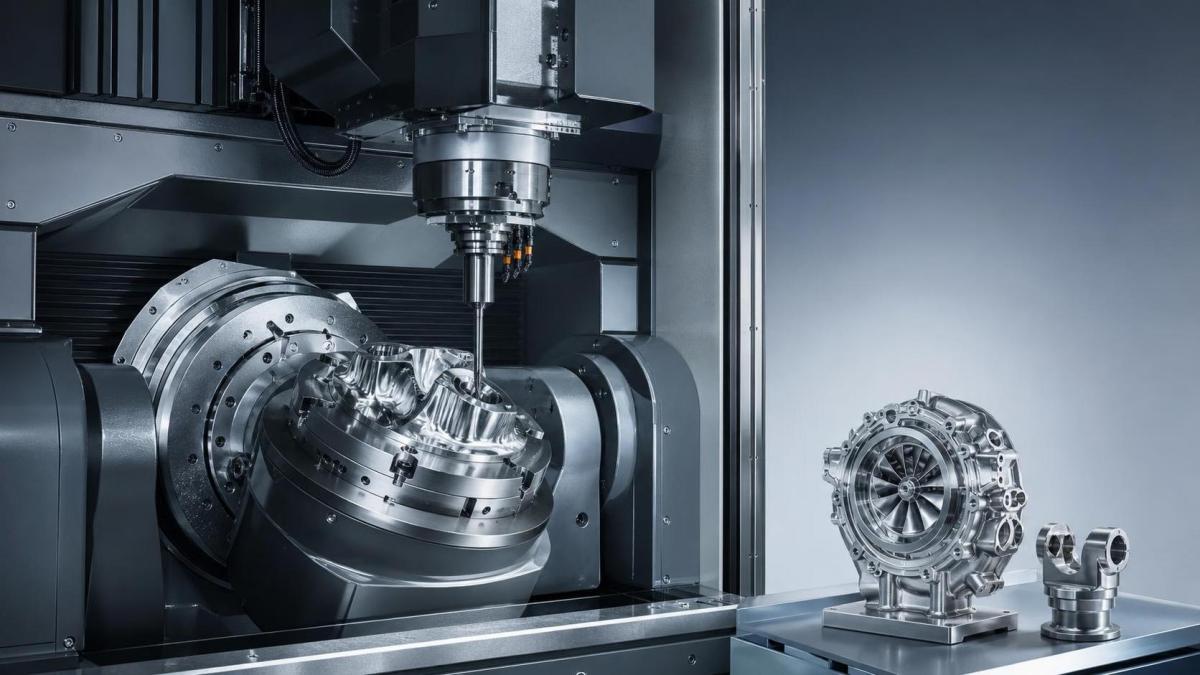
In multi-axis machining, kinematic architecture directly influences precision retention. Trunnion-style tables, swivel heads, table-table configurations, and head-table designs each bring trade-offs in stiffness, collision risk, moving mass, part size accommodation, and thermal behavior.
For smaller, high-precision parts, a trunnion configuration may offer good accessibility and compact motion loops, but it also places strong demands on rotary axis calibration and fixture height control. For larger or heavier workpieces, head-table designs may reduce the burden on rotary tables, but dynamic performance depends heavily on the head structure and spindle support.
Evaluators should look at the center of gravity throughout the motion range, not only static load capacity. A machine can have acceptable axis travels yet still perform poorly when the workpiece mass shifts rotary behavior or when tool length amplifies angular error at the cut point.
Questions worth asking during evaluation include:
- How does the machine maintain accuracy at extreme rotary positions?
- What is the manufacturer’s method for volumetric calibration?
- How sensitive is the configuration to tall fixtures or long tools?
- Are there known performance differences between positional 3+2 work and true simultaneous 5-axis cutting?
Static accuracy is not enough; dynamic accuracy is where many decisions fail
For tight-tolerance geometries, published positioning accuracy values can be misleading if taken in isolation. What matters in production is dynamic contouring accuracy while axes accelerate, decelerate, and blend motion under cut.
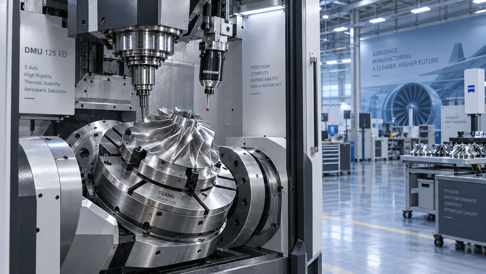
This is especially important for parts with freeform surfaces, sculpted pockets, impellers, blisks, orthopedic geometries, or sealing features where motion smoothness directly affects both form and finish. Servo tuning, look-ahead functions, jerk control, and interpolation algorithms all influence the final result.
A technically sound evaluation should include evidence from circular interpolation, 5-axis test parts, or equivalent machine capability verification methods. In some industries, users also rely on ballbar testing, laser interferometer measurement, and volumetric compensation checks. The exact acceptance method varies, but the principle is consistent: no machine should be judged only by no-load axis data.
Another overlooked point is acceleration behavior with real spindle-tool-holder assemblies. On a lightweight test cut, many machines appear stable. Under long-reach tools, hard materials, or interrupted cuts, limitations in structural damping and control response become visible quickly.
Thermal control is often the deciding factor in repeatability
In demanding machining environments, thermal behavior is one of the clearest separators between machines that can make a good first part and machines that can sustain capability across a shift. Spindle growth, ballscrew heating, coolant temperature variation, ambient fluctuation, and rotary axis heating all affect the tool center point.
Technical evaluators should examine whether the machine incorporates:
- spindle and structure temperature monitoring;
- active or model-based thermal compensation;
- coolant temperature control;
- stable hydraulic and lubrication thermal management;
- documented warm-up and stabilization procedures.
Thermal compensation itself should not be treated as a marketing checkbox. The relevant issue is how well compensation matches actual plant conditions. A compensation model validated in a controlled showroom may not behave the same way in a factory exposed to door openings, seasonal variation, nearby heat sources, or aggressive high-duty-cycle machining.
When tolerances are tight, the evaluator should ask for drift data over time, not just one-time accuracy values. This is particularly important for suppliers intending to support international customers in regions with different shop-floor climate conditions.
Spindle performance should be matched to the material and feature mix
High spindle speed is useful only when it aligns with part geometry, material, and tool strategy. A machine intended for aluminum aerospace parts, hardened steel molds, titanium components, and stainless medical work cannot be evaluated with one generic spindle metric.
More meaningful factors include:
- power and torque across the usable speed range;
- bearing design and thermal stability;
- tool taper suitability;
- runout performance at the spindle nose and in-tool condition;
- vibration characteristics during fine finishing and roughing.
For complex parts with deep cavities or slender tools, spindle-toolholder interface quality becomes critical. HSK, BIG-PLUS, CAPTO, and other systems may each make sense depending on the process, but the decision should be tied to rigidity, repeatability, and tool change consistency, not preference alone.
If the target application includes difficult alloys, chatter suppression and torque delivery at lower-to-mid spindle speeds may matter more than headline RPM. By contrast, for precision aluminum components with fine finishing passes, dynamic balance and thermal steadiness may dominate.
Rotary axes deserve closer scrutiny than linear axes in many evaluations
On complex parts, a large share of geometric error originates in the rotary system. Backlash, encoder resolution limits, clamping repeatability, axis squareness, and centerline offset all influence final part quality. This is one reason why nominally capable 5-axis machines can produce inconsistent results on orientation-sensitive features.
Technical evaluators should pay attention to:
- rotary axis braking or clamping mechanism performance;
- repeatability after repeated indexing;
- error behavior under payload and eccentric loading;
- kinematic calibration interval and serviceability;
- interaction between rotary motion and probing compensation.
For simultaneous machining, smoothness through rotary reversal zones is especially important. Any hesitation or micro-instability can appear as witness marks, faceting, or subtle profile error. These issues are not always visible in simple acceptance demonstrations, so test parts should resemble the target application as closely as possible.
Software compatibility is no longer secondary
For a Multi-axis Machining Center for Complex Parts, hardware capability can be undermined by weak software integration. The machine control, CAM postprocessor, digital setup workflow, probing routines, and inspection feedback loop need to operate as a system.
In practice, evaluators should verify:
- CAM postprocessor maturity for the exact machine kinematics;
- support for tool center point management and coordinate transformations;
- collision avoidance reliability at the control and programming level;
- closed-loop integration with probing and offset correction;
- compatibility with shop-floor data systems and traceability requirements.
Postprocessor quality is often underestimated during capital equipment selection. Yet many real-world performance problems come from poorly tuned post output, inconsistent rotary handling, or excessive smoothing that alters geometry. A technically strong machine paired with immature postprocessing can create endless prove-out delays and unstable part quality.
Where regulated industries are involved, software validation and change control may also affect the buying decision. Exact compliance requirements depend on sector and geography, and any specific certification expectations should be treated as application-dependent and verified separately.
Probing, measurement, and compensation strategy should be part of the machine decision
Complex tight-tolerance parts are rarely made successfully by machining alone. In-process probing, tool measurement, work offset management, broken-tool detection, and sometimes on-machine verification are part of the capability package.
That does not mean on-machine measurement replaces a CMM. It means the machine should support a disciplined process for reducing setup variation and detecting drift before scrap occurs. For low-volume high-mix production, this can significantly affect both yield and setup time. For serialized or traceable parts, the data path from probing to quality record also matters.
Evaluators should be careful not to overestimate automatic compensation. Compensation can stabilize a capable process, but it cannot rescue poor rigidity, unstable fixturing, or a weak thermal design.
Fixturing access and chip evacuation are often underestimated in complex-part machining
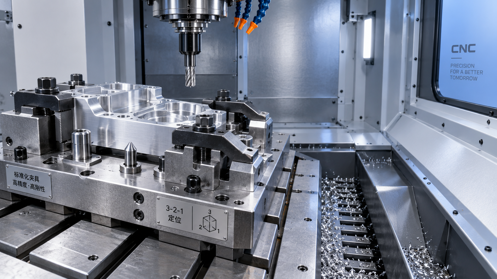
Many machine selections look sound until real fixtures and chips enter the equation. Tight-tolerance work on complex parts frequently involves awkward clamping, low-contact workholding, or orientation changes that complicate chip evacuation. If chips accumulate in deep cavities or around locators, accuracy and surface integrity can degrade quickly.
The machine should therefore be assessed for:
- working envelope usability with realistic fixture height;
- spindle access at the required tilt angles;
- chip removal behavior in vertical, horizontal, and angled positions;
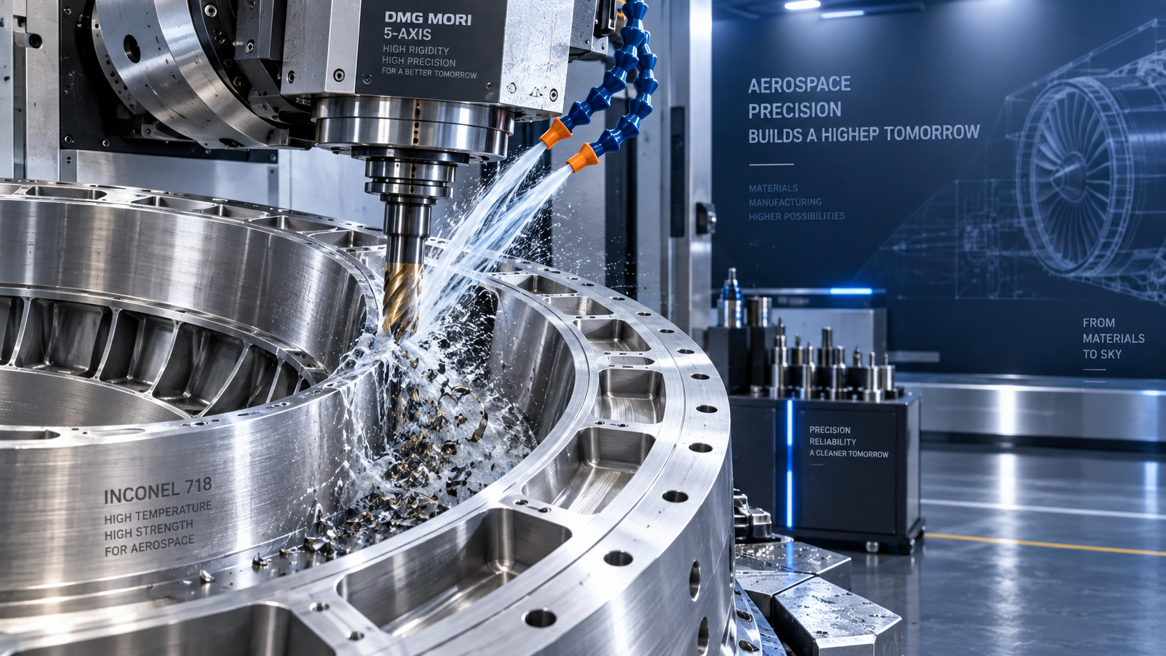
- coolant delivery effectiveness for deep-feature machining;
- operator visibility during setup and prove-out.
For technical evaluators, this is an area where simulated reach studies and collision checks should be supplemented by practical trials. A machine may be technically able to reach a feature, but only with such fragile tooling or awkward fixturing that process capability becomes marginal.
Reliability and service support are technical issues, not just commercial ones
When a machine is expected to hold tight tolerances on complex parts, uptime is only one dimension of reliability. The more important issue is whether accuracy can be restored quickly after service events, crashes, spindle replacement, or rotary maintenance.
That makes service structure part of technical evaluation. Relevant questions include:
- How is geometric requalification performed after intervention?
- Are local service teams capable of multi-axis calibration?
- What is the parts lead time for encoders, spindle assemblies, and rotary components?
- How often do users need to revalidate machine kinematics in actual production?
For global operations or cross-border procurement, this point becomes even more important. A machine sourced competitively from another region may still create hidden risk if field calibration support is weak or if spare parts availability is uncertain.
Acceptance criteria should reflect the part, not the catalog
One of the clearest signs of a mature evaluation process is a customized acceptance protocol. Standard machine acceptance tests provide a baseline, but they do not fully answer whether the machine fits a specific tight-tolerance application. Where possible, buyer and supplier should define trial conditions around representative materials, tool overhangs, feature types, cycle durations, and inspection methods.
Relevant standards for machine tool accuracy and test methodology may apply depending on region, machine type, and customer requirements, but exact standard selection should be confirmed case by case. If a supplier cites compliance with a specific standard, that claim should be verified in the context of the intended application rather than accepted as a complete performance guarantee.
The strongest evaluations usually combine three layers: machine accuracy verification, application test cutting, and process capability review after repeat runs. That combination reveals whether the machine can not only produce the target part, but produce it consistently enough for the intended commercial model.
What technical evaluators should avoid
Several recurring errors appear in multi-axis machine selection:
- treating spindle speed, axis count, or travel as the primary decision criteria;
- judging machine capability from sample parts that do not match the real feature set;
- ignoring thermal behavior because initial demo parts measure well;
- underestimating the effect of postprocessor quality and control tuning;
- assuming all 5-axis machines are equally competent in simultaneous machining;
- separating machine evaluation from fixturing, tooling, probing, and inspection strategy.
In tight-tolerance manufacturing, the machine is only one part of the process system. But it is the part that defines the limits of everything else. That is why the right evaluation question is not whether the machine is advanced, but whether it is stable, measurable, supportable, and well matched to the actual tolerance risk in the part family.
For teams responsible for technical selection, the best decision usually comes from a narrower and more disciplined comparison than the market initially encourages. Fewer machines may qualify than expected. That is not a weakness in the process. It is usually a sign that the evaluation is finally aligned with production reality.
Recommended for You
 How to Design Cost-Effective Fixtures That Maintain Cycle Time in Mass ProductionCNC Machining Technology Center
 Is Learning CNC Programming Worth It for Shop Owners Seeking Higher Margins?CNC Machining Technology Center
 CNC Machine Arrival Inspection: Check Shipping Damage, Accuracy, Safety, and DocumentsCNC Machining Technology Center
 How to Select a Machine Tool for Aerospace Parts with Tight Tolerances?Machine Tool Industry Editorial Team
 How to Select CNC Equipment for High-Mix, Low-Volume ProductionCNC Machining Technology Center
 Can CNC Machining Inconel Control Tool Wear in High-Temperature Aerospace Parts?CNC Machining Technology Center

Aris Katos
Future of Carbide Coatings
15+ years in precision manufacturing systems. Specialized in high-speed milling and aerospace grade alloy processing.
▶
Is Learning CNC Programming Worth It for Shop Owners Seeking Higher Margins?CNC Machining Technology Center▶
How to Select CNC Equipment for High-Mix, Low-Volume ProductionCNC Machining Technology Center▶
Can CNC Machining Inconel Control Tool Wear in High-Temperature Aerospace Parts?CNC Machining Technology Center▶
How Automated Precision Machining Maintains Tolerance in High-Mix ProductionCNC Machining Technology Center▶
CNC Programming Explained: From CAD Models to Reliable Shop-Floor ToolpathsCNC Machining Technology Center
Mastering 5-Axis Workholding Strategies
Join our technical panel on Nov 15th to learn about reducing vibrations in thin-wall components.

Providing you with integrated sanding solutions
Before-sales and after-sales services
Comprehensive technical support